

Image processing apparatus and method therefor
a technology of image processing and apparatus, applied in the field of image processing, can solve the problems of requiring an enormous processing time and unable to finish the processing within a practical time, and achieve the effect of suppressing the processing tim
- Summary
- Abstract
- Description
- Claims
- Application Information
AI Technical Summary
Benefits of technology
Problems solved by technology
Method used
Image

Examples
first embodiment
[Arrangement of Apparatus]
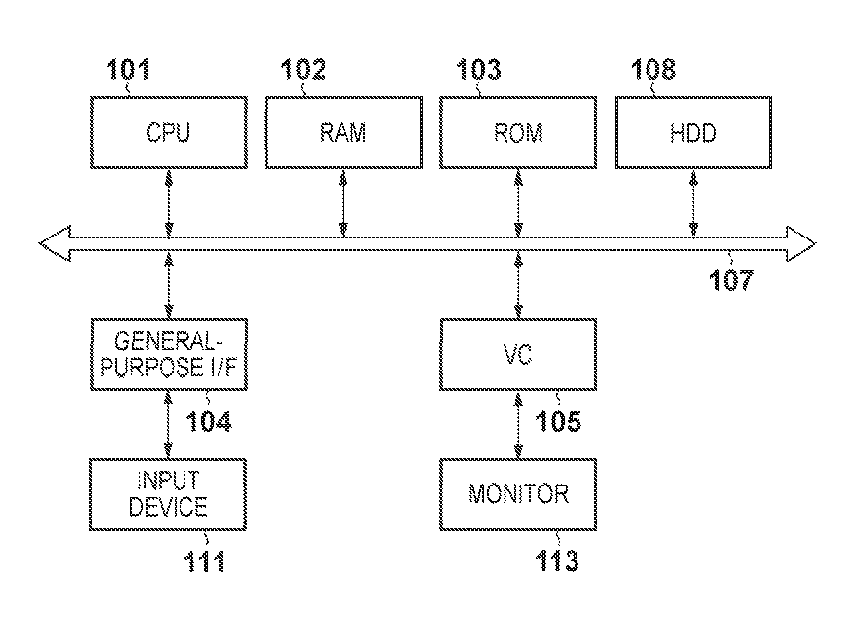
[0024]The arrangement of an image processing apparatus according to an embodiment will be described with reference to the block diagram of FIG. 1.
[0025]A microprocessor (CPU) 101 executes various kinds of programs including an operating system (OS) by using a random access memory (RAM) 102 as a work memory. These programs are stored in a read only memory (ROM) 103 or a nonvolatile memory such as a hard disk drive (HDD) 108. The CPU 101 controls the components (to be described later) via a system bus 107. The HDD 108 stores a program for implementing image generation processing (to be described later), the spectral characteristic data of a light source and object, and the like.
[0026]A general-purpose interface (I / F) 104 is, for example, a serial bus interface such as USB (Universal Serial Bus), to which an input device 111 such as a mouse or a keyboard is connected. A video card (VC) 105 is a video interface, to which a monitor 113 such as a liquid crystal d...
second embodiment
[0072]Image processing according to the second embodiment of the present invention will be described below. The same reference numerals as in the first embodiment denote the same constituent elements in the second embodiment, and a detailed description of them will be omitted.
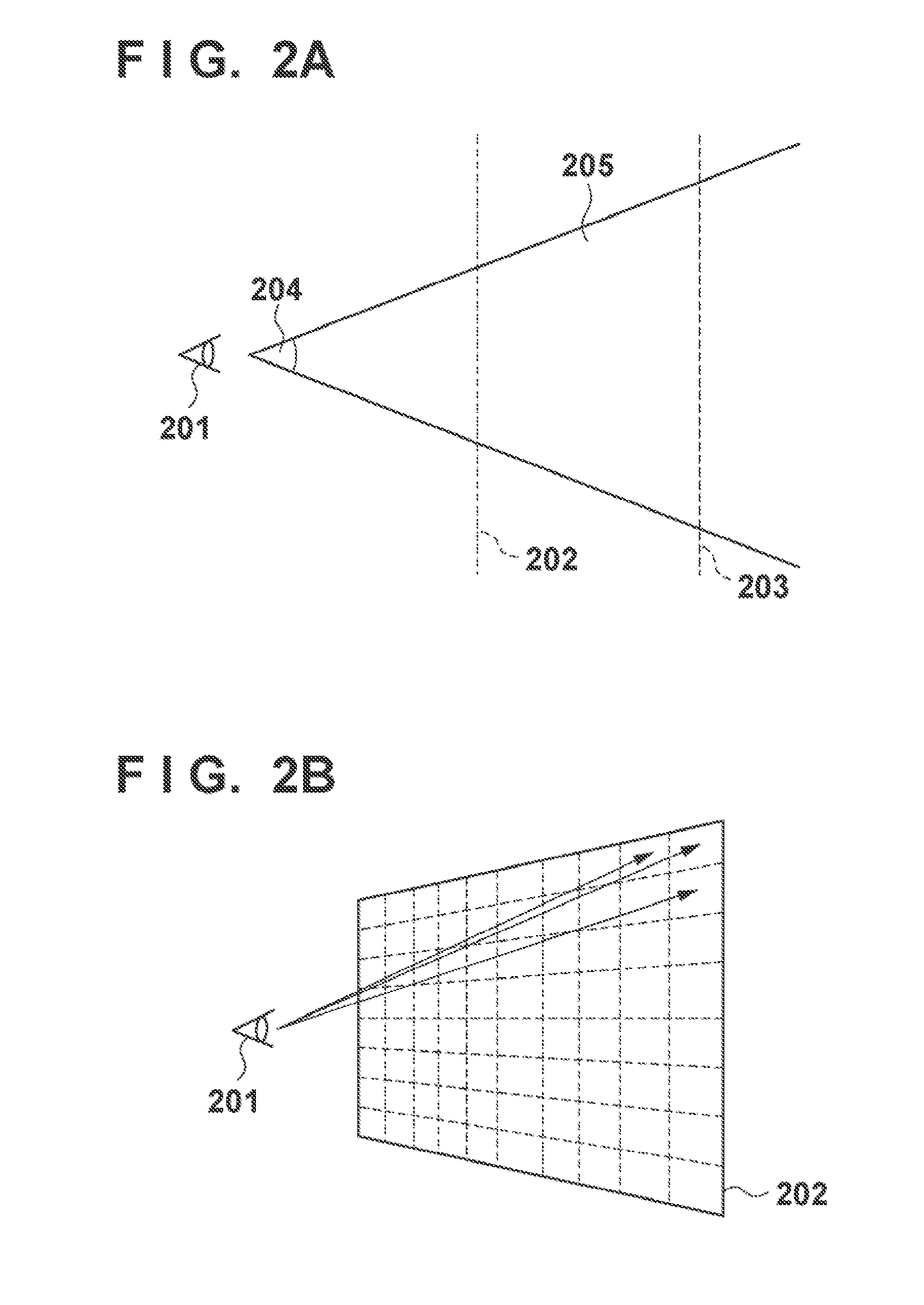
[0073]The second embodiment will exemplify a method of controlling the processing of tracing back a ray in accordance with the distance between a view point 201 and an object. An outline of processing by the ray-tracing method according to the second embodiment will be described with reference to FIGS. 8A and 8B.
[0074]FIG. 8A shows a state in which there are objects 704 and 705 in a rendering area 205 viewed from the view point 201. The object 704 is located close to a front clip surface 202, that is, located close to the view point 201, whereas the object 705 is located close to a rear clip surface 203, that is, located far from the view point 201.
[0075]FIG. 8B shows the rendering result on the objects 704 and...
third embodiment
[0083]Image processing according to the third embodiment of the present invention will be described below. The same reference numerals as in the first and second embodiments denote the same constituent elements in the third embodiment, and a detailed description of them will be omitted.
[0084]The third embodiment will exemplify a method of controlling the processing of tracing back a ray in accordance with the number of times of diffused reflection. An outline of the processing by the ray-tracing method according to the third embodiment will be described with reference to FIGS. 11A and 11B.
[0085]FIG. 11A shows the behavior of reflection by an object 908 having many fine recesses and projections on the surface. When incident light 906 strikes the object 908, the incident light 906 is scattered by the fine recesses and projections on the surface to generate reflected light 907 in every direction. Diffused reflection is a phenomenon that occurs on a lusterless object, which includes mat...
PUM
 Abstract
Description
Claims
Application Information