Recording apparatus and liquid ejection head

a technology of liquid ejection and recording apparatus, which is applied in the direction of printing and inking apparatus, etc., can solve the problems of increasing the discharge of ink for recovery, affecting the quality of ink recovery, and affecting the impact of ink droplets, so as to inhibit the increase of the viscosity of ink

Inactive Publication Date: 2012-05-10
CANON KK
View PDF4 Cites 100 Cited by
  • Summary
  • Abstract
  • Description
  • Claims
  • Application Information

AI Technical Summary

Benefits of technology

[0008]Thus, it is an object to provide a recording apparatus capable of solving the above problems and inhibiting viscosity increase of an ink to conduct high-quality recording over a long period of time.

Problems solved by technology

In addition, when foggy ink mist that is ejected from the ejection orifices but does not reach a recording medium adheres to around the ejection orifices in plenty, the ink mist adhered hinders the ejection of the ink to cause impact deviation of ink droplets.
However, when such a suction ejection-recovery operation that ink is discharged from ejection orifices of a recording head is conducted during the recording for preventing the viscosity increase of the ink, the long-term continuous printing is hindered.
In the recording head of the full-multi type, a great number of ejection orifices are arranged corresponding to the overall width of the recording medium, so that discharge of ink for recovery increases to greatly increase running cost.
Even in the method disclosed in Japanese Patent Application Laid-Open No. 2006-95857, however, it is difficult to inhibit ejection failure caused by evaporation of water from the ink in a non-recording state where the ink is not ejected over a long period of time.
When ejection of the ink is started after the non-recording state for the long period of time, lowering of recording quality and impact deviation may be caused in some cases because the viscosity of ink droplets just after the starting is increased.
This variation is considered to adversely affect the recording quality on a recording medium.

Method used


Image

  • Recording apparatus and liquid ejection head
  • Recording apparatus and liquid ejection head
  • Recording apparatus and liquid ejection head

Examples


second embodiment

[0046]FIGS. 4A and 4B schematically illustrate the construction of a recording head according to a second embodiment of the present invention, in which FIG. 4A schematically illustrate, on an enlarged scale, the top of the neighborhood of a first opening 9, and FIG. 4B schematically illustrates a section taken along line 4B-4B in FIG. 4A. Incidentally, the same portions in this embodiment as in the first embodiment are given the same characters, and the detailed descriptions thereof are omitted.

[0047]In this embodiment, the circulation flow path 11 is not exposed to the outside from the surface layer 14′ of the flow path forming portion 14 of the first embodiment. However, a second opening 31 having an opening area larger than that of the first opening 9 is provided at a position corresponding to the first opening 9 in the surface layer 14′. The opening corresponding to the circulation flow path 11 may not be formed in the surface layer 14′, or the opening corresponding to the circu...

third embodiment

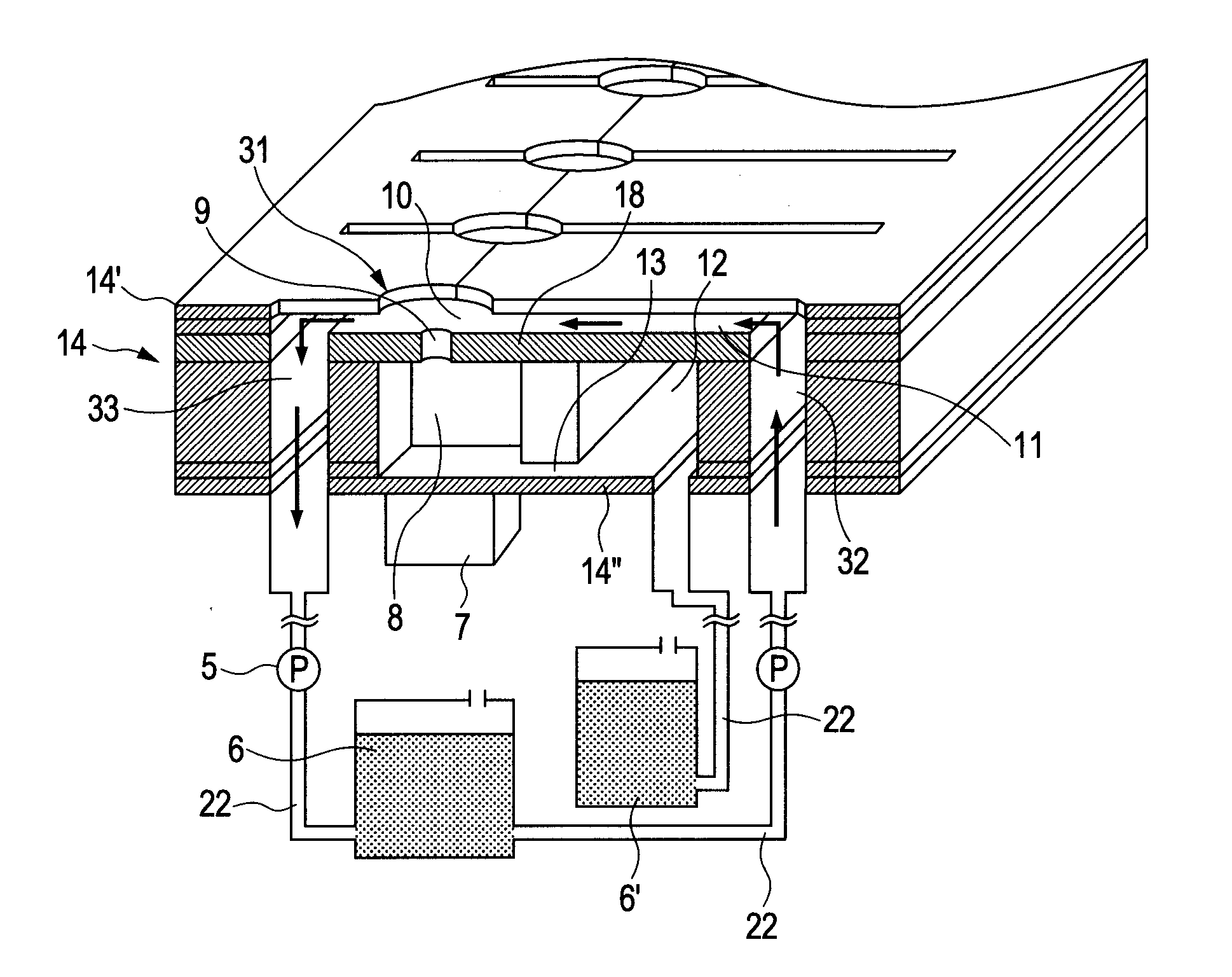
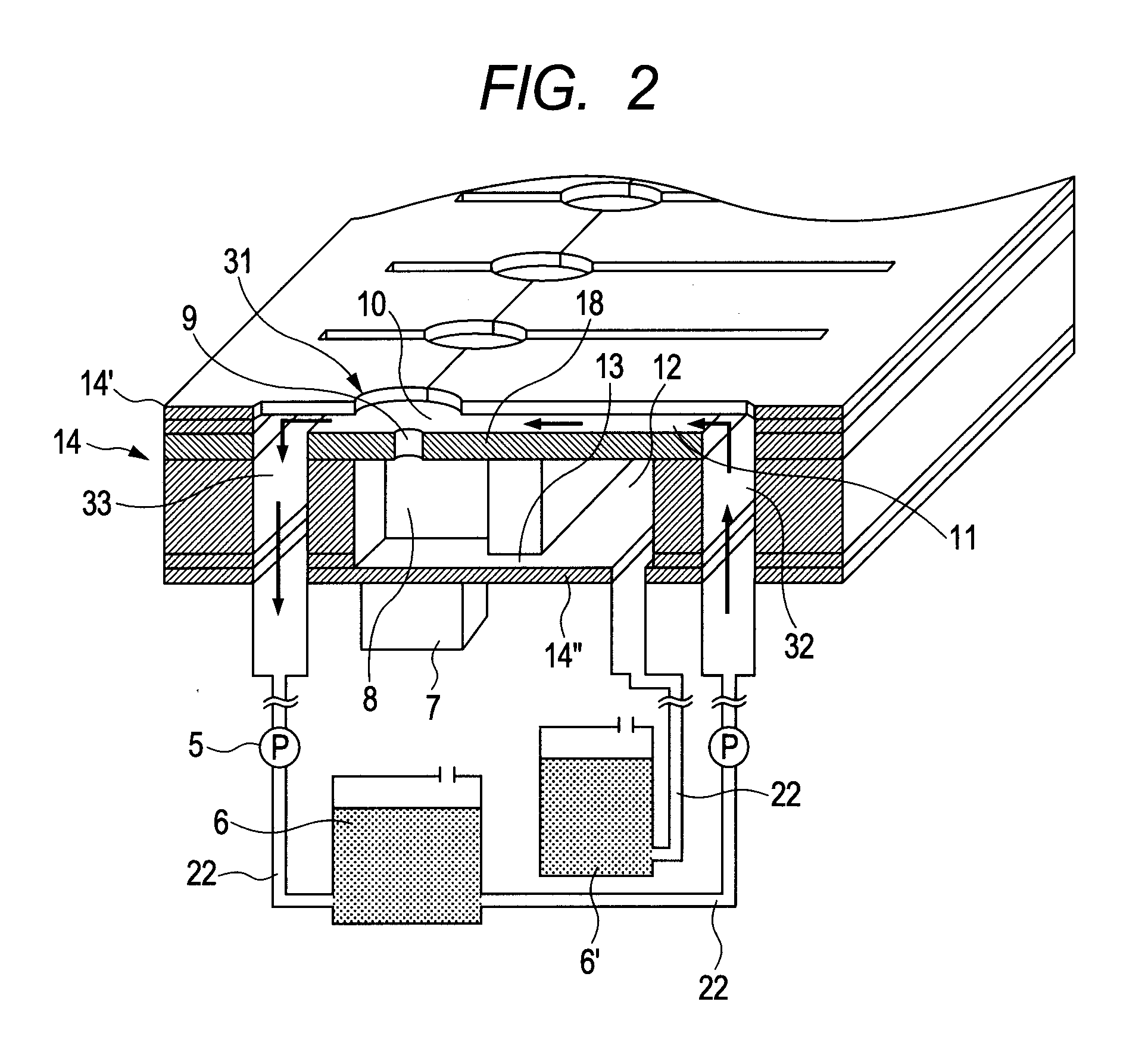
[0049]With respect to the same constructions as in the above-described embodiments, the descriptions thereof are omitted. In the embodiment illustrated in FIG. 5, a pump is also provided as a flow unit of the ink in the ink flow path 22 connecting the ink tank 6′ to the common liquid chamber 12 in the recording head of the first embodiment illustrated in FIG. 2. The ink is thereby caused to flow to the circulation flow path 11 through the first opening 9 and the ink reservoir 10 from the individual liquid chamber 8 even in a non-ejecting state as illustrated in FIG. 5. Therefore, the ink in the first opening 9 can be caused to flow without local retention. It can thereby be effectively inhibited to cause a concentration distribution by the retention of the ink in the first opening 9. In addition, the influence of the viscosity increase of the ink by the evaporation from the portions exposed to the outside in the ink reservoir 10 and the circulation flow path 11 can be more effective...

fourth embodiment

[0051]FIGS. 6A and 6B typically illustrate a recording head according to a fourth embodiment of the present invention, in which FIG. 6A is a plan view of the recording head, and FIG. 6B schematically illustrates a section taken along line 6B-6B in FIG. 6A. With respect to the same constructions as in the above-described embodiments, the descriptions thereof are omitted.

[0052]In the first embodiment, the circulation flow path is provided for each first opening 9. In this embodiment, a circulation flow path 11 is provided so as to communicate with a plurality of the first openings 9 by connecting the circulation flow paths 11 to one another. Specifically, the common ink inlet portion 32 and the common ink outlet portion 33 are provided so as to put the plurality of the first openings 9 arranged between them, and a circulation flow path 11 extending from the common ink inlet portion 32 to the common ink outlet portion 33 is provided so as to communicate with all the ink reservoirs 10.

[...


PUM


Abstract

A recording apparatus including an ink tank and a recording head having a flow path forming portion that has an ejection orifice plate having plural ink ejection orifices and a liquid chamber provided for each orifice to supply ink to the orifices, and an energy generating element for ejecting ink in the chamber. A surface layer of the flow path forming portion opposes to the outside of the plate. An opening is provided opposing to the orifices in the surface layer. An ink reservoir is provided between the plate and the opening. A circulation flow path communicating with the ink reservoir is provided. The area of the opening is larger than that of the orifice. Both ends of the circulation flow path are respectively connected to inlet and outlet portions connected to the circulation flow path. The inlet and outlet portions and liquid chamber are connected to the ink tank.

Description

BACKGROUND OF THE INVENTION[0001]1. Field of the Invention[0002]The present invention relates to a recording apparatus that ejects an ink to conduct recording and a liquid ejection head from which a liquid is ejected.[0003]2. Description of the Related Art[0004]A thermal system and a piezoelectric element system are representative of an ink jet recording system (Drop-On-Demand system) in which an ink is intermittently ejected from ejection orifices provided in a recording head according to recording information to apply the ink to a recording medium such as paper. In a recording apparatus using a recording head of such a system, the viscosity of an ink in the vicinity of the ejection orifices may be increased in some cases by evaporation of water in the ink in the vicinity of the ejection orifices and transfer of the ink attending thereon, whereby such a condition that the ink is not ejected from the ejection orifices or the amount of the ink ejected does not reach a desired value m...

Claims


Application Information

Patent Timeline
Patent Type & Authority Applications(United States)
IPC IPC(8): B41J2/18
CPCB41J2/1404B41J2/14233B41J2/145B41J2202/12B41J2/1433B41J2/18
Inventor KASHU, RYOTASASAGAWA, NAOTOKARITA, SEIICHIROAOKI, TAKATSUNAOKUSHIMA, SHINGONISHITANI, EISUKE
Owner CANON KK
Why Eureka
Try Eureka