

Transfer type inkjet recording method and transfer type inkjet recording device
a technology of inkjet recording and transfer medium, which is applied in the direction of printing, etc., can solve the problems of considerable difference in apparent texture between the recording medium and the transfer medium, and achieve the effect of reducing the work load of users
- Summary
- Abstract
- Description
- Claims
- Application Information
AI Technical Summary
Benefits of technology
Problems solved by technology
Method used
Image

Examples
example 1
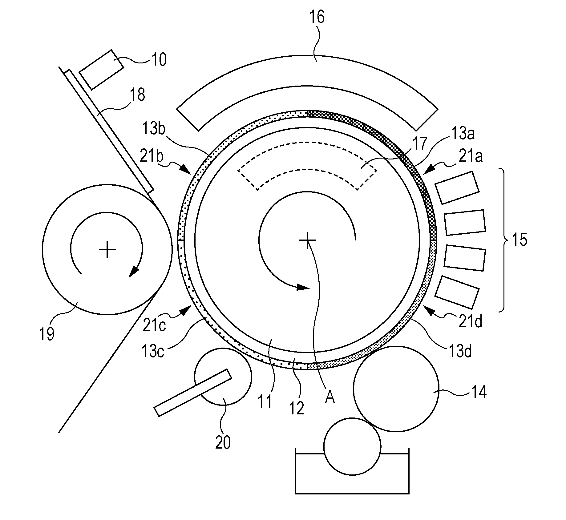
[0105]In Example 1, the transfer type inkjet recording device illustrated in FIG. 4 was used. The configuration and the like of the recording device are specifically described below.
Support Member and Intermediate Transfer Body
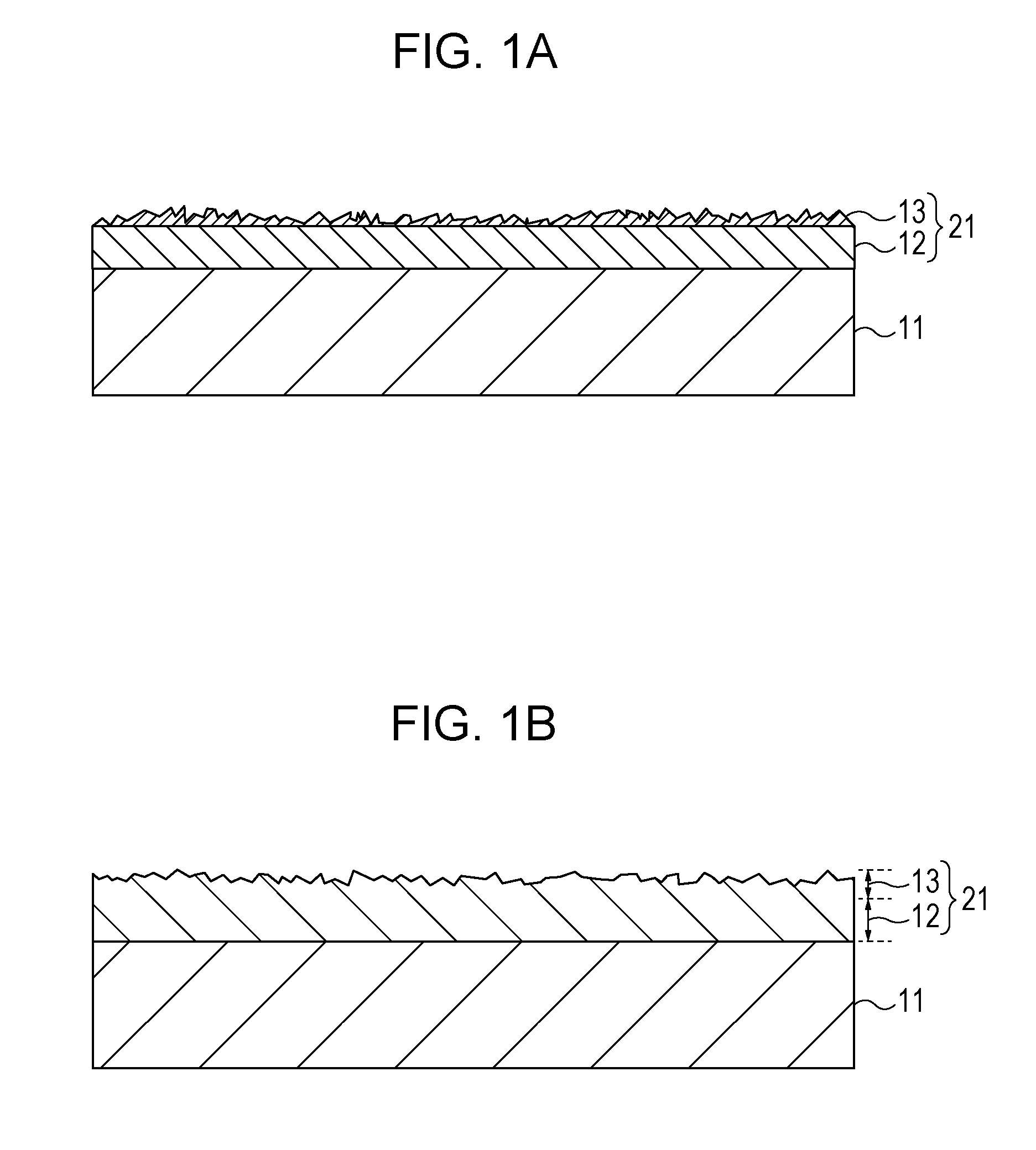
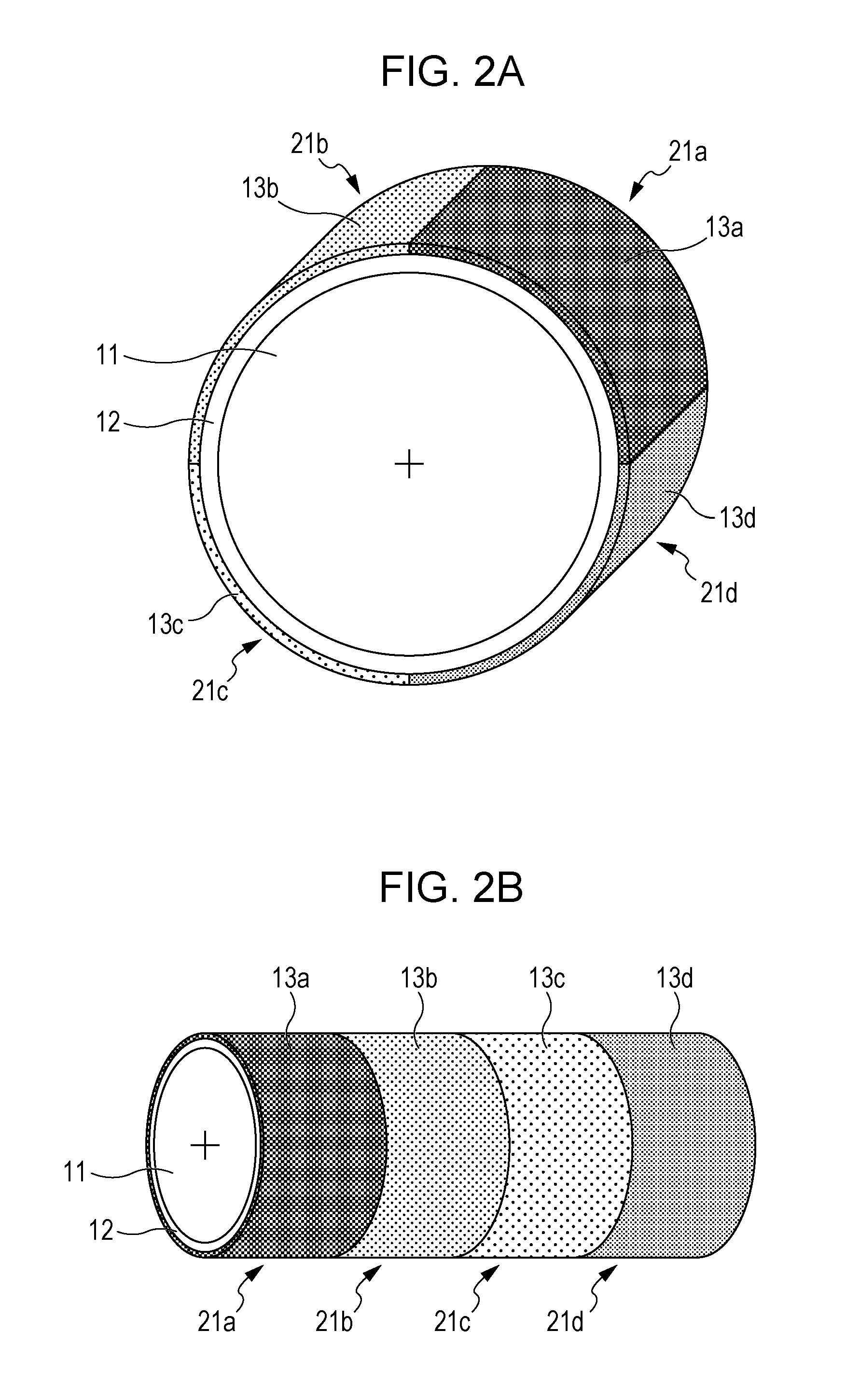
[0106]Four intermediate transfer bodies 21a to 21d containing a common surface layer member 12 and concavo-convex layers 13a to 13d formed on the surface of the surface layer member 12 were fixed to the external surface of a rotatable support member 11 having the shape of a drum for use. In order to distinguish the concavo-convex layers and the intermediate transfer bodies from concavo-convex layers and intermediate transfer bodies used in other Examples, the four concavo-convex layers are denoted by the reference characters 13a-1 to 13d-1 and the four intermediate transfer bodies are denoted by the reference characters 21a-1 to 21d-1, respectively.
[0107]For the support member 11, a cylindrical drum containing an aluminum alloy was used. The surface layer memb...
example 2
[0124]In Example 2, the four intermediate transfer bodies (21a-1 to 21d-1) of Example 1 were changed to four intermediate transfer bodies (21a-2 to 21d-2) shown in Table 4. The support member 11 and the surface layer member 12 of the intermediate transfer bodies are the same as those of Example 1. Concavo-convex layers (13a-2-13d-2) of the intermediate transfer bodies (21a-2 to 21d-2) were formed by performing photolitho processing of optical curable urethane-modified acrylic resin (manufactured by TOAGOSEI Co., LTD.) in the same manner as in Example 1. Similarly as in Example 1, an optical cured product of the above-described urethane-modified acrylic resin was separately produced, and the elastic modulus thereof was measured. The elastic modulus at 25° C. of the optical cured product was 330 MPa. An image was formed on each recording medium in the same manner as in Example 1 other then the above, and the image quality was evaluated. The evaluation results are shown in Table 4.
example 3
[0127]An image was formed on each recording medium in the same manner as in Example 1, except using two kinds of intermediate transfer bodies (21b-2 and 21d-2) among the four intermediate transfer bodies (21a-2 to 21d-4), and the image quality was evaluated. The evaluation results of Comparative Example 2 above only using the one kind of the intermediate transfer body 21b-2 are also shown as a comparative example in Table 5.
TABLE 5Printing targetPaper typeCoatedCoatedCoatedCoatedpaper apaper bpaper cpaper dRa [μm]0.261.192.092.79TransferExample 3Intermediate transfer21b-221b-221d-221d-2bodybodyRa [μm]0.990.992.712.71Image quality3535evaluationComparativeIntermediate transfer21b-221b-221b-221b-2Example 2bodyRa [μm]0.990.990.990.99Image quality3522evaluation
[0128]As is seen from Table 5, the same or higher image quality was always obtained to a wide variety of paper types also in Example 3 using two kinds of intermediate transfer bodies different in the center line surface roughness R...
PUM
 Abstract
Description
Claims
Application Information