Case structure and fan frame fixing module

Active Publication Date: 2012-05-10
DELTA ELECTRONICS (THAILAND) PUBLIC CO LTD
View PDF8 Cites 8 Cited by
  • Summary
  • Abstract
  • Description
  • Claims
  • Application Information

AI Technical Summary

Benefits of technology

[0006]The present invention provides a case structure to be assembled in a simp

Problems solved by technology

If the heat energy fails to be effectively dissipated away, the elevated operating temperature may result in damage, reduced use life or deteriorated performance of the electronic components.
Under this ci

Method used


Image

  • Case structure and fan frame fixing module
  • Case structure and fan frame fixing module
  • Case structure and fan frame fixing module

Examples


Example

[0024]The present invention will now be described more specifically with reference to the following embodiments. It is to be noted that the following descriptions of preferred embodiments of this invention are presented herein for purpose of illustration and description only. It is not intended to be exhaustive or to be limited to the precise form disclosed.

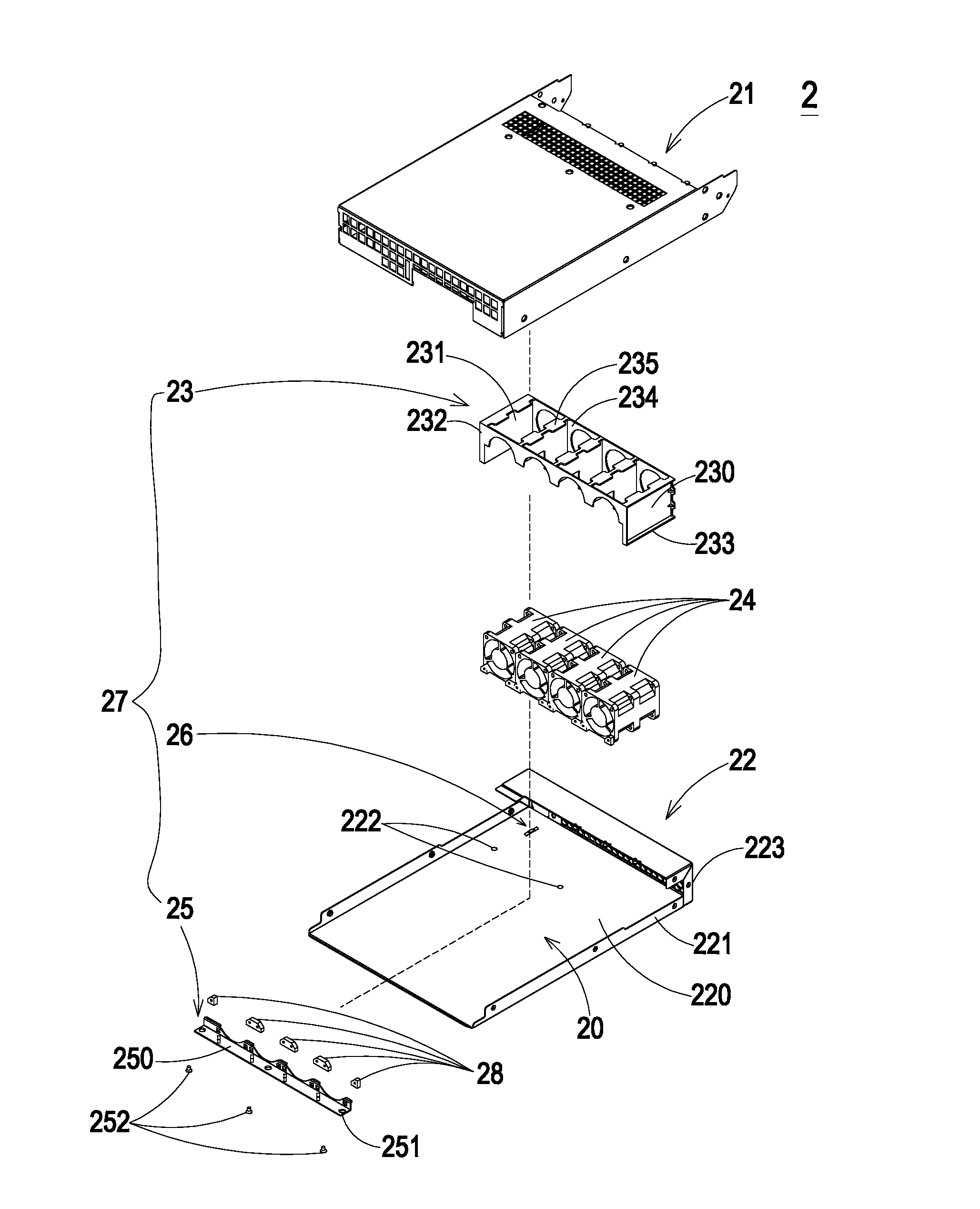
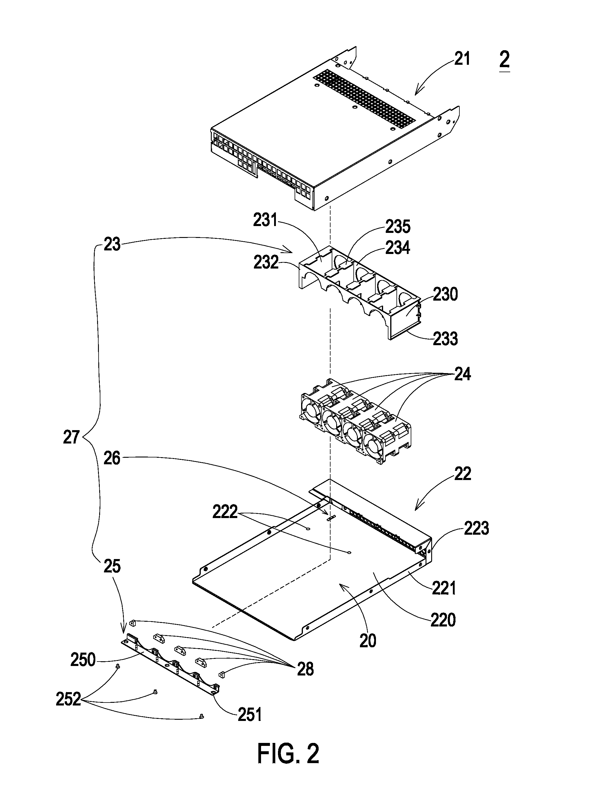
[0025]FIG. 2 is a schematic exploded view illustrating a case structure according to a first embodiment of the present invention. As shown in FIG. 2, the case structure 2 includes a second housing 21 and a first housing 22. After the second housing 21 and the first housing 22 are combined together, a receptacle 20 is defined for accommodating a fan frame fixing module 27. In this embodiment, the fan frame fixing module 27 includes a fan frame 23, a positioning part 26 and an auxiliary part 25. The positioning part 26 and the auxiliary part 25 are disposed on a first bottom surface 220 of the first housing 21. The positioning part...


PUM


Abstract

A case structure includes a first housing and a fan frame fixing module. The fan frame fixing module includes a fan frame, a positioning part and an auxiliary part. The positioning part is disposed on the first housing. The auxiliary part is disposed on the first housing. The fan frame urges against the first housing and the positioning part, and the auxiliary part urges against the fan frame so that the fan frame is fixed on the first housing.

Description

FIELD OF THE INVENTION[0001]The present invention relates to a case structure and a fan frame fixing module, and more particularly to a case structure and a fan frame fixing module that are easily assembled and have reduced vibration.BACKGROUND OF THE INVENTION[0002]With increasing development of science and technology, the amount of data to be processed by data processing devices (e.g. computer systems or servers) are gradually increased. After a data processing device (e.g. a computer systems or a server) is used for a long term, a great amount of heat energy generated by the electronic components may be accumulated within the data processing device. If the heat energy fails to be effectively dissipated away, the elevated operating temperature may result in damage, reduced use life or deteriorated performance of the electronic components. For effectively transferring the heat energy to the ambient air, a fan is installed within the data processing device. In particular, for enhanc...

Claims


Application Information

Patent Timeline
IPC IPC(8): F01D25/28
CPCF04D25/0613F04D29/601G06F1/20H05K7/20172F04D29/668
Inventor LI, RANKITTI, PLOYJERMSRIKUL
Owner DELTA ELECTRONICS (THAILAND) PUBLIC CO LTD
Why Eureka
Try Eureka