Pivoting structural cellular wall for wind energy generation

a technology of cellular wall and wind energy, which is applied in the direction of reaction engines, machines/engines, mechanical equipment, etc., can solve the problems of not creating an advantageous efficient solution, failure to meet the needs of the industry, and unresolved use, so as to improve wind speed, increase energy yield, and yield greater energy density

Inactive Publication Date: 2012-05-10
RUTHERFORD JOHN
View PDF7 Cites 3 Cited by
  • Summary
  • Abstract
  • Description
  • Claims
  • Application Information

AI Technical Summary

Benefits of technology

[0013]The present invention is unique in that it is structurally different from other known devices or solutions. More specifically, the present invention is unique due to the presence of: (1) It's hexagonal and triangular geometry; (2) Tensegrity cable members; (3) It's minimal horizontal wind disturbance shape; (4) The creation of the cylindrical void area for the turbines within the cellular structure; (5) The structure locates turbines close to one another in a dense packed grid; (6) The pivoting cellular wall has a wide triangular base with a fixed pivot which keeps the pivot in tension and the outlying vertexes of the base in compression; and (7) It's wide height to width ratio. Furthermore, the process associated with the aforementioned invention is likewise unique and different from known processes and solutions. More specifically, the present invention process owes its uniqueness to the fact that it: (1) Minimizes wind speed disturbance and turbulence; (2) Wind flows around structural members in a minimally disturbed state; (3) Wind flows cause the entire structure to pivot and stay facing into the wind and (4) The wall can have increased flex and sway.
[0015]It is still further an object of the present invention to be lighter and more economical to construct.

Problems solved by technology

Some of these solutions attempt to install the turbine on top of a single post or truss tower, but these solutions fail to meet the needs of the industry because you can only put one turbine on one tower.
These solutions ignore the benefits of placing multiple turbines within a cellular wall structure and building structures with multiple turbines.
There are numerous alternative designs in prior art which, while imaginative still do not create an advantageous efficient solution.
The geometry that they use does not resolve issues of rotational and vibrational instability and simply limits the number of multiple turbines.

Method used


Image

  • Pivoting structural cellular wall for wind energy generation
  • Pivoting structural cellular wall for wind energy generation
  • Pivoting structural cellular wall for wind energy generation

Examples


Embodiment Construction

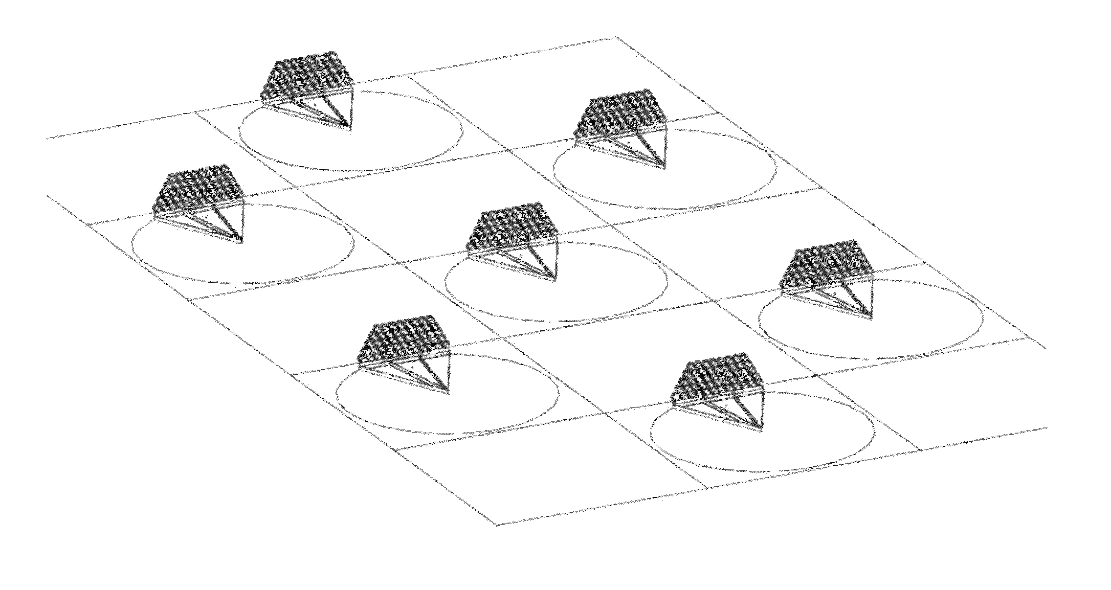
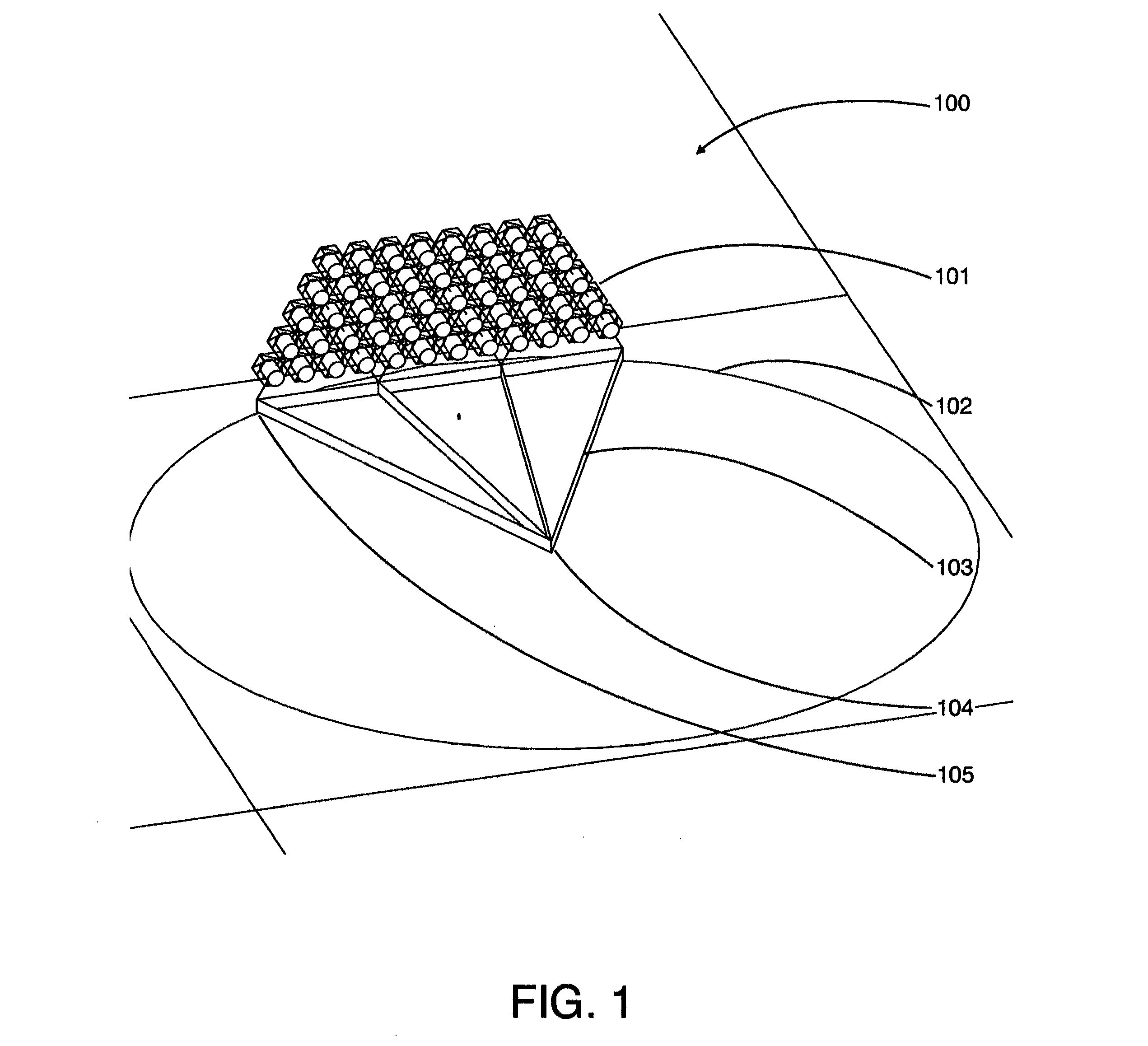
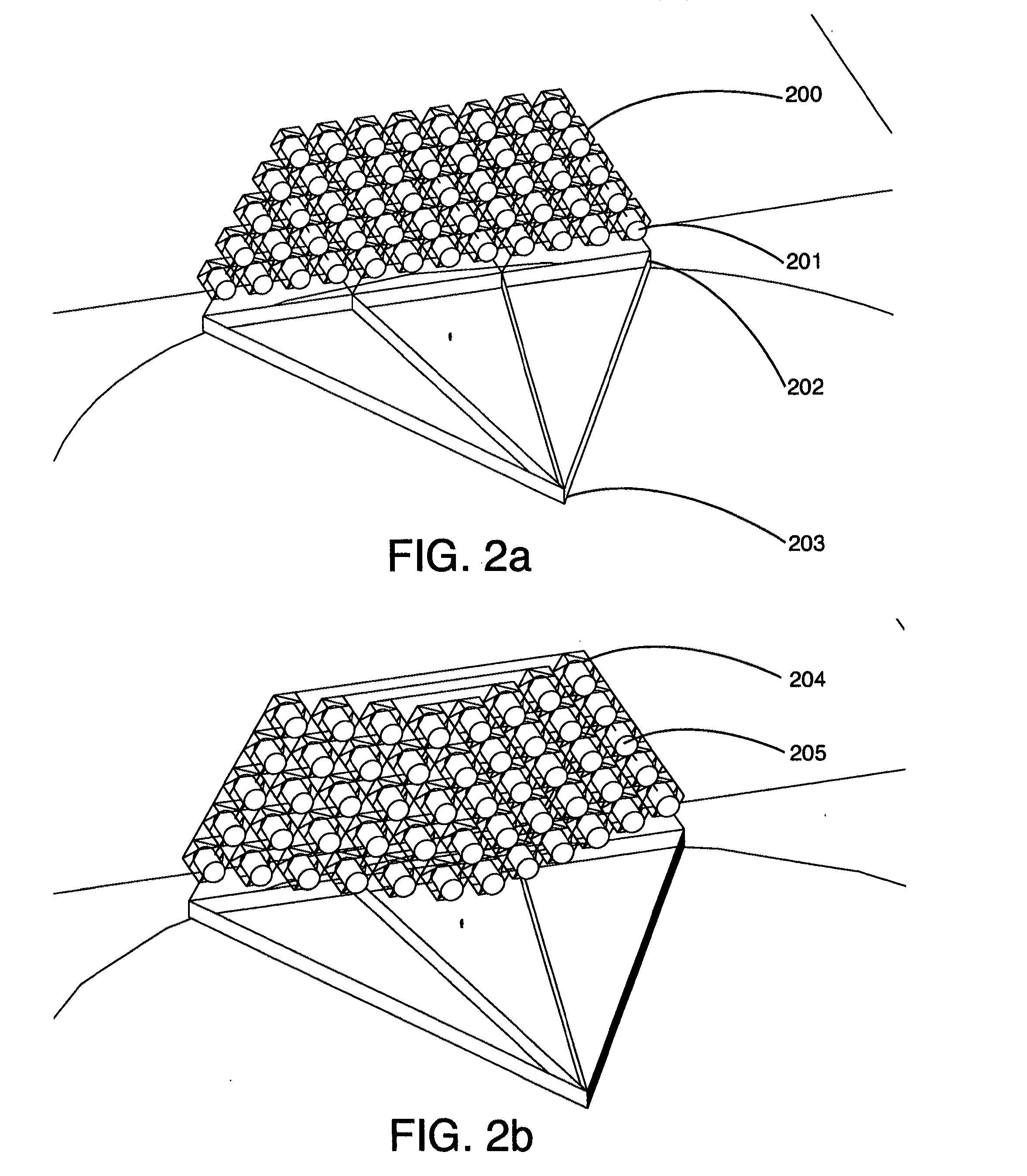
[0028]The present invention is directed to be a Pivoting Structural Cellular Wall For Wind Energy Generation

[0029]In its most complete form, the present invention device is made up of the following components, foundations, compressive structural members, tensegrity cable structural members and hexagonal triangular modules. These members are arranged into triangular or hexagonal shapes with welded, bolted or cable connections. These shapes are then arranged into three dimensional modules which are also based on hexagonal and triangular geometry. The modules are unitized to resolve structural forces within themselves and as a component of the larger structural grid assembly. The stacking of modules forms a complete structural wall. The top / outer modules have additional structural members and the additional of role of resolving tensegrity forces when tensegrity cables are used in interior modules. It should further be noted that: while the main structural materials are steel and steel ...


PUM

PropertyMeasurementUnit
energy yieldaaaaaaaaaa
tensionaaaaaaaaaa
vibrational instabilityaaaaaaaaaa

Abstract

The present invention relates to a device and method associated with the device. It is a wall for collecting wind energy, holds multiple wind turbines at increased heights, the device also pivots around a central point and keeps the turbines aligned into the direction of the wind. This device can be used to increase the yield of energy collected from the wind and to place wind turbines in stronger winds. The device enables turbines to be located within the structure. The rotation is around a center pivot point with the outer vertexes of the triangle free to move. With respect to the method, the modular cells locate the wind turbines in higher wind speeds. The wind flows around and through the cell structure creating beneficial vortexes. The wind is converted into energy at the turbine, at the conclusion of these steps wind energy is converted into electrical power.

Description

CROSS REFERENCE TO RELATED APPLICATION[0001]This application claims the benefit of provisional patent application Ser. No. 61 / 399,267, filed Jul. 8, 2010 by the present inventor, which is incorporated by reference.BACKGROUND OF THE INVENTION[0002]1. Field of the Invention[0003]The present invention relates generally to a pivoting structural cellular wall for wind energy generation.[0004]2. Background-Prior ArtPatent NumberIssue DatePatentee7,075,1892006Heronemus6,749,3992004Heronemus6,100,6002000PflanzDes 305,4191990Korneski4,550,2591985Bertels4,340,8221982Gregg4,323,3311982Schachle4,220,8701980Kelly4,110,6311978Salter3,883,7501975Uzzell1,345,0221920OliverBACKGROUND-SUMMARY[0005]Currently there are a number of solutions for installing wind turbines. Some of these solutions attempt to install the turbine on top of a single post or truss tower, but these solutions fail to meet the needs of the industry because you can only put one turbine on one tower. This leads to solutions where th...

Claims


Application Information

Patent Timeline
Patent Type & Authority Applications(United States)
IPC IPC(8): F03D11/04B23P17/04
CPCF03D1/04F05B2240/122Y10T29/49F05B2240/40Y02E10/72F05B2240/132
Inventor RUTHERFORD, JOHN
Owner RUTHERFORD JOHN
Why Eureka
Try Eureka