
Panel assembly and accessories

a panel and accessories technology, applied in the field of panel assembly, can solve the problems of damage to the structure next to the working site, time-consuming, and difficult to remove the cover panel from the base for replacement, and achieve the effects of easy assembly and replacement, increased or reduced or replaced, and short period of tim

Active Publication Date: 2012-05-17
CHUANG MING CHING
View PDF7 Cites 19 Cited by
  • Summary
  • Abstract
  • Description
  • Claims
  • Application Information

AI Technical Summary

Benefits of technology

[0026]The primary object of the present invention is to provide a panel assembly which can be increased or reduced or replaced within short period of time. By assembling different sizes of panels and arranging different types of arrangements, different gaps can be defined so that shelves and accessories are connected to the panel assembly.
[0027]The panel assembly of the present invention is easily to be assembled and replaced, and the change of the panel assembly is flexible.

Problems solved by technology

A conventional panel assembly sued in decoration uses a cover panel fixed to the base directly and the cover panel is difficult to be removed from the base for replacement conveniently.
When the users want to change or replace the patterns on the cover panel, both of the cover panel and the base are need to be replaced and this is a time consuming task and significant material will be discarded.
Furthermore, the removal of the cover panel and the base may damage the structure next to the working site.
However, the cited references cannot provide solutions for quickly replacement of the decoration panels, storage panels, and display panels.
Nevertheless, when assembling the racks and the panels, the panels cannot be quickly disengaged from the racks.
Besides, the panels have multiple holes whose positions are fixed so that when the panels have to be shifted or connected to different ways, the holes of the panels that to be connected cannot be in alignment with each other.
Therefore, the inherent problems are not solved.

Method used


Image

  • Panel assembly and accessories
  • Panel assembly and accessories
  • Panel assembly and accessories

Examples


Embodiment Construction

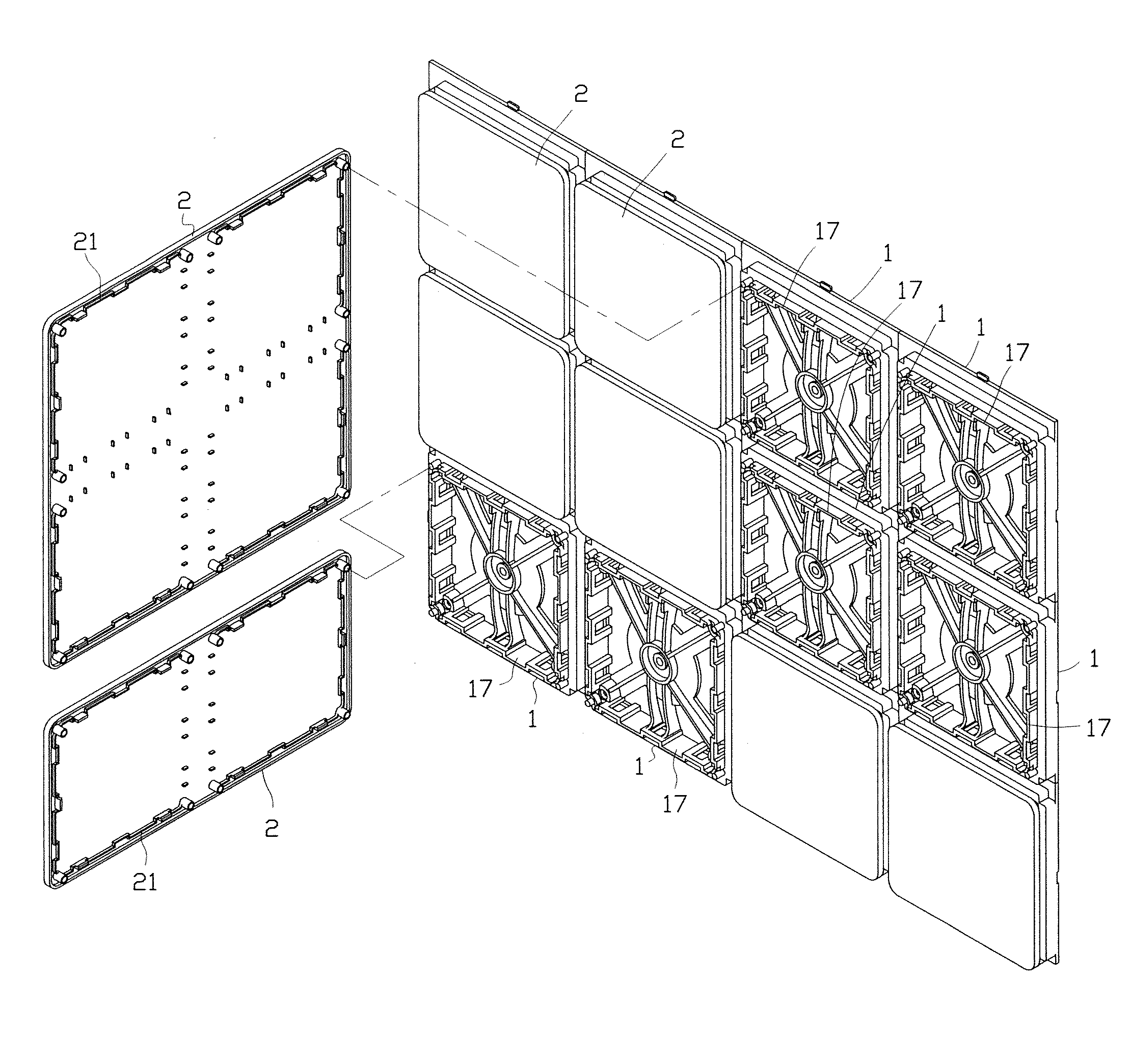
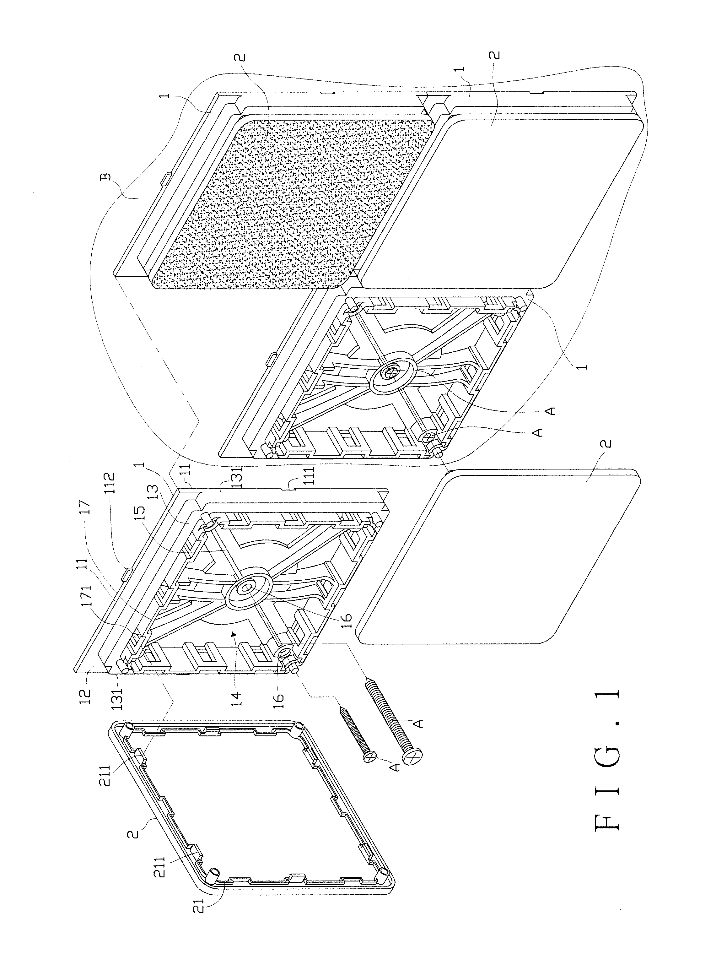
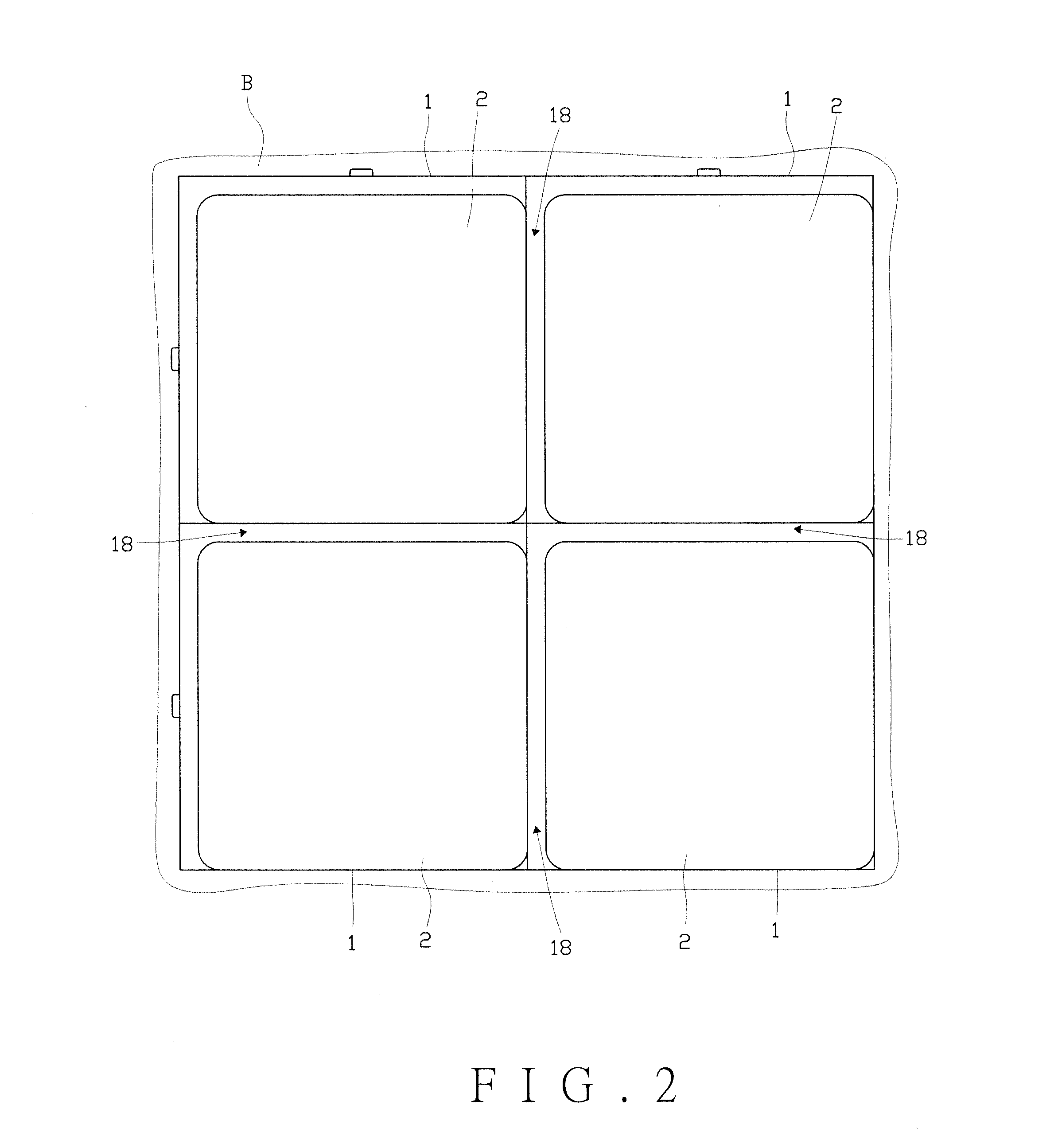
[0052]Referring to FIGS. 1 and 2, the panel assembly of the present invention comprises multiple base boards 1 and each base board 1 has four sides 11 to form a base face 12. A rectangular wall 13 extends from the base face 12 and has a hollow portion 14. A fixing unit 15 is located in the hollow portion 14 and connected to the rectangular wall 13. The fixing unit 15 has more than one fixing holes 16. The base boards 1 can be fixed to a wall “B” by extending screws “A” through the fixing holes 16. A first connection member 17 is located at the conjunction portion between the rectangular wall 13 and the hollow portion 14. The first connection member 17 has a connection hole 171 and a path 18 is defined between two adjacent rectangular walls 13. In this embodiment, the two adjacent sides 131 of the rectangular wall 13 are in flush with the two adjacent sides 11 of the base board 1, so that the path 18 is defined between the other two adjacent sides 11 of the base board 1 and the recta...


PUM


Abstract

A panel assembly includes multiple base boards, multiple cover panels, multiple shelves and multiple accessories so as to be fixed to a wall. The multiple base boars and the multiple cover panels define a path, a space and a gap. The path, the space and the gap communicate with each other. Sand the shelves or the accessories are inserted into the path, the space and gap. The panel assembly can be quickly assembled and replaced to change the arrangements and suitable for decoration and display or storage.

Description

FIELD OF THE INVENTION[0001]This application is a continuation in part of my application filed Jun. 24, 2008, Ser. No. 12 / 144,899, currently pending.[0002]The present invention relates to a panel assembly and the accessories thereof, and more particularly, to a panel assembly suitable for decoration, display and storage.BACKGROUND OF THE INVENTION[0003]A conventional panel assembly sued in decoration uses a cover panel fixed to the base directly and the cover panel is difficult to be removed from the base for replacement conveniently. When the users want to change or replace the patterns on the cover panel, both of the cover panel and the base are need to be replaced and this is a time consuming task and significant material will be discarded. Furthermore, the removal of the cover panel and the base may damage the structure next to the working site.[0004]U.S. Pat. Nos. 4,063,393, 4,114,247, 4,913,576 and 5,623,800 disclose some of the panel assemblies which are classified in the int...

Claims


Application Information

Patent Timeline
IPC IPC(8): E04C2/38
CPCA47B96/20A47B2200/0055A47F5/0846G09F15/0006G09F7/02G09F7/08E04F13/088
Inventor CHUANG, MING-CHING
Owner CHUANG MING CHING
Learn More