Device for transmitting torques

a technology of transmitting torque and torque, which is applied in the direction of measurement devices, work measurement, instruments, etc., can solve the problems of efficiency loss and measurement errors, and achieve the effect of reducing the time required for exchanging coils, reducing the effort required for calibrating devices, and simple and precise manners

Inactive Publication Date: 2012-05-17
THYSSENKRUPP EGM
View PDF4 Cites 6 Cited by
  • Summary
  • Abstract
  • Description
  • Claims
  • Application Information

AI Technical Summary

Benefits of technology

[0024]Moreover, an advantageous further embodiment of the invention provides that the bearing block has at least one holding device for holding at least one coil. This results in the advantage that the arrangement of the coil or the coils can take place in a simple and precise manner so that the effort required for calibrating the device can be reduced.
[0025]Further, an advantageous further embodiment of the invention provides that the coil can be removed from the holding device and, particularly, the coil can be removed from the holding device in the assembled state of the bearing block. Thereby it is achieved that the time required for exchanging the coil is considerably reduced. In addition, it is thereby achieved that the device can be adapted in a fast and simple manner to the requirements of the measurement. Further, it is thereby possible to reduce the maintenance times and, moreover, to reduce the maintenance costs.
[0026]Moreover, another advantageous further embodiment of the invention provides that the measuring device includes at least one measuring sensor which is integrated in the bearing block. Through the measuring sensor it is possible to determine a measurement valve by which a conclusion can be drawn on the torque transmitted by the shaft. It is advantageous here to use an electronic measuring sensor which provides a computer-assisted recording of the measurand and thus simplifies the subsequent evaluation of the measurement.
[0027]Further, another advantageous further embodiment of the invention is characterized in that the measuring sensor is a magnetic field sensor configured for sensing a change of a magnetic field caused by a change of the torque applied to the shaft. In this manner it is achieved that a change of the magnetic field can be measured, by which a conclusion can be drawn as to the torque which is applied to the shaft and which influences the magnetic field. Thereby it is possible to carry out the measurement almost exclusively in an electronic manner, whereby mechanical wear of the device is minimized or excluded. Consequently, the service life of the device is improved.
[0028]Moreover, an advantageous further embodiment of the invention provides that the material of the shaft is or contains 50NiCr13 and / or 45CrNiMo16. Through the material selection for the shaft based on the materials described herein, it is achieved that the shaft can be very well adapted to the device requirements. In addition, the shaft is thereby provided with a good machinabilty, whereby the manufacturing costs can be reduced. Further, it was found that the mentioned materials are very well suited for a long-term magnetization of the shaft.
[0029]A useful further embodiment of the invention provides that the shaft is through-hardened at least in sections and has in particular at least in sections a hardness of ≧58 HRC according to DIN EN 10109. By hardening the shaft, the mechanical properties for the measurement of the torque are improved, whereby the field of application of the device is extended.

Problems solved by technology

However, the devices have the disadvantage that a large space is required for measuring the torque applied to the shaft, whereby efficiency losses and measuring errors can arise which have to be compensated for by comparatively laborious means.

Method used


Image

  • Device for transmitting torques
  • Device for transmitting torques

Examples


Embodiment Construction

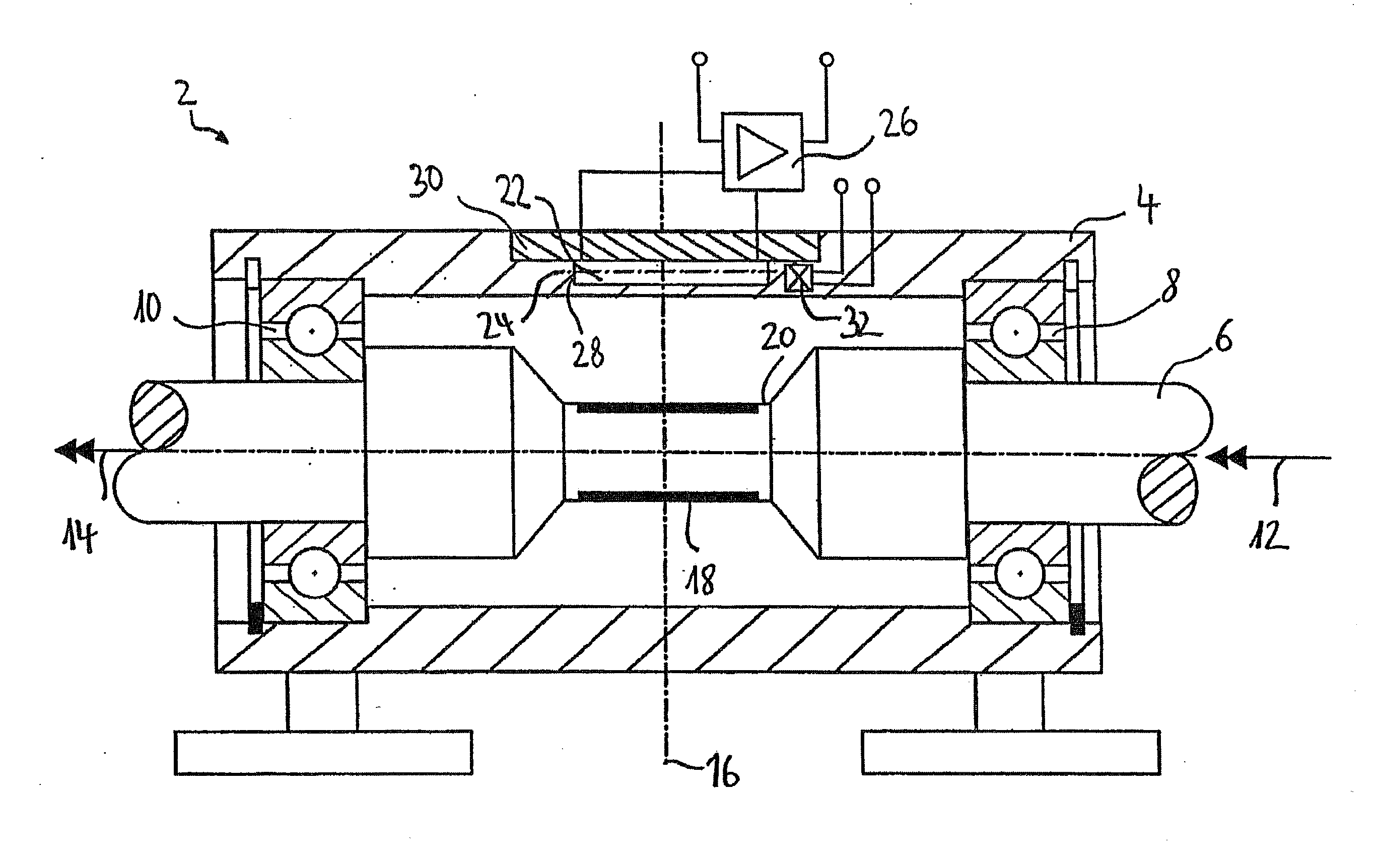
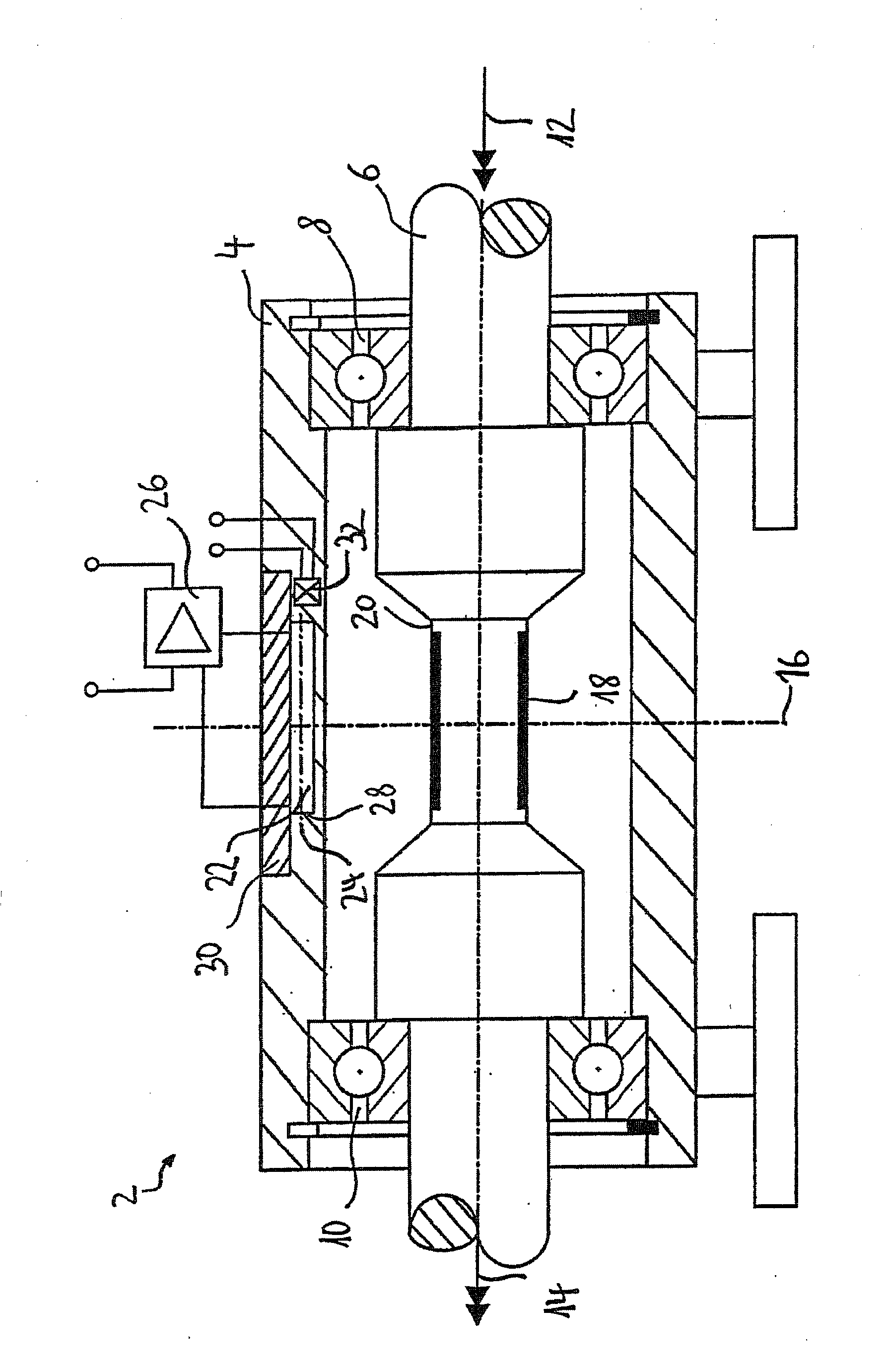
[0036]The illustrated embodiment of device 2 includes a bearing block 4 in which a torque-transmitting shaft 6 is rotatably mounted by a first shaft bearing 8 and a second shaft bearing 10. For the first shaft bearing 8 and the second shaft bearing 10, one grooved ball bearing is used in each case.

[0037]The torque-transmitting shaft 6 transmits a drive torque 12 generated by a drive. For a better overview, the drive and the connection of the torque-transmitting shaft 6 to the drive are not illustrated.

[0038]The drive torque 12 is transmitted by the torque-transmitting shaft 6 and is output as output torque 14 at the output end of the shaft. To simplify the illustration, the output end of the shaft is likewise not illustrated.

[0039]Between the first shaft bearing 8 and the second shaft bearing 10, the torque-transmitting shaft 6 is built symmetrically to a center plane 16. Centered between the first shaft bearing 8 and the second shaft bearing 10, the torque-transmitting shaft 6 has ...


PUM

PropertyMeasurementUnit
lengthaaaaaaaaaa
axial lengthaaaaaaaaaa
diameteraaaaaaaaaa

Abstract

Device for transmitting torques with a torque-transmitting shaft and a bearing block for mounting the shaft. The device includes a measuring device for measuring a torque applied to the torque-transmitting shaft. The measuring device for measuring the torque device is at least partially integrated in the bearing block.

Description

CROSS-REFERENCE TO RELATED APPLICATIONS[0001]This application is a continuation of application no. PCT / EP2009 / 005966, filed Aug. 18, 2009, which claims the priority of German application no. 10 2008 056 302.1, filed Nov. 7, 2008, and each of which is incorporated herein by reference.FIELD OF THE INVENTION[0002]The invention relates to a device for transmitting torques including a torque-transmitting shaft. More particularly, the invention relates to a device for transmitting torques including a torque-transmitting shaft, a bearing block for mounting the tongue-transmitting shaft, and a measuring device for measuring a torque applied to the torque-transmitting shaft.BACKGROUND OF THE INVENTION[0003]Such devices are in particular known in the area of measurement technology where they absorb a torque at their input which they transmit to the output of the device at which the input torque can be received as output torque. For transmitting the input torque to the output of the device, a ...

Claims


Application Information

Patent Timeline
Patent Type & Authority Applications(United States)
IPC IPC(8): G01L3/10
CPCG01L3/105G01L3/102
Inventor EICKE, ANDREASHEIDEMANN, JOACHIM
Owner THYSSENKRUPP EGM
Why Eureka
Try Eureka