Pipe support base

a technology of supporting base and pipe, which is applied in the direction of machine supports, other domestic objects, mechanical apparatus, etc., can solve the problems of piping losing its fixture to the wooden support, wood corroding, bolt loss, etc., and achieves the effects of preventing damage to the waterproofing of the roof, easy movement or removal, and very economical pipe support bas

Active Publication Date: 2012-05-17
ADVANCE CO LTD
View PDF12 Cites 36 Cited by
  • Summary
  • Abstract
  • Description
  • Claims
  • Application Information

AI Technical Summary

Benefits of technology

[0017]In this way, the support base is only installed to the surface of a roof, thus obviating work such as rooftop surface processing and, as a result, completely preventing damage to roof waterproofing.
[0018]With buildings, renovation of roof waterproofing is required at a certain point in time after construction is complete. Even upon renovation, the support base of the present invention does not require roof surface processing as it is simply placed on the surface of a roof. As such, the support base can be easily moved or removed without interfering with waterproofing.
[0019]By forming a plurality of grooves on a single support base, grooves conforming to commercially-available pipe fastener specifications can be selected from this plurality of grooves and the corresponding surface can be used by facing it upward. As such, a variety of types of fasteners can be made to correspond with a single support base, making the inventive pipe support base very economical.

Problems solved by technology

(1) Structures in which piping is fixed to wood blocks are both inexpensive and easy to set up. However, wind, rain, and sunlight cause the wood to corrode and the bolts to be lost, thereby potentially causing the piping to lose its fixture to the wooden base.
(2) With methods for producing mountings by mixing concrete and filling the interior of mold forms with that concrete, mountings which conform to actual conditions can be installed, but such methods take much time and effort.
(3) There are also certain methods in which pipe mountings are constructed together with roof waterproofing as a single unit. With such methods, renovation of roof waterproofing requires cumbersome work such as spreading out sheets of material and covering the periphery of the mounting and, further, this waterproofing may be incomplete as a result.

Method used


Image

  • Pipe support base
  • Pipe support base
  • Pipe support base

Examples


Embodiment Construction

[0027]The preferred embodiments of the present invention will hereafter be explained in reference to the drawings.

[0028](1) Support Base

[0029]The structure of support 1 will first be explained.

[0030](1-1) Basic Shape

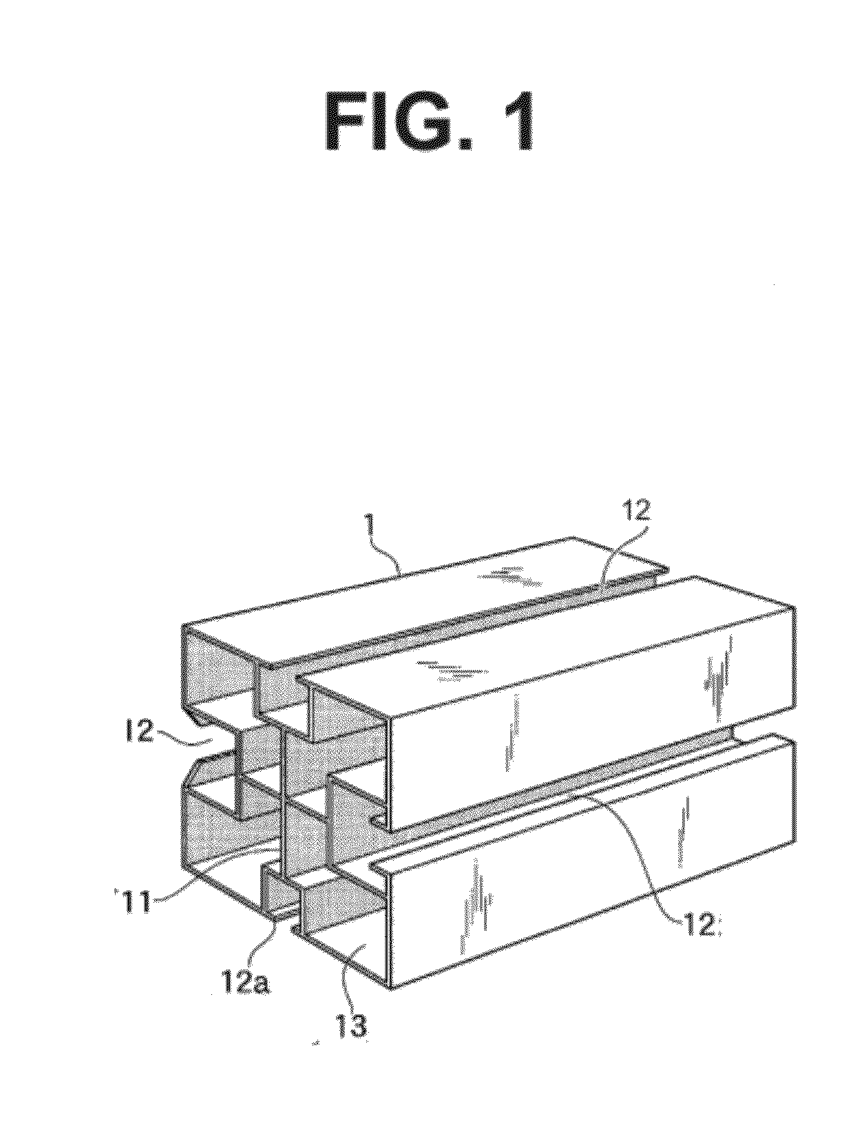
[0031]The basic shape of pipe support base 1 supporting pipe P is a cross section enclosed by a rectangular hollow cylindrical body. This cylindrical body material is a lightweight material constituted of a synthetic such as ABS resin or AES resin or constituted of thin steel plates. A cross-shaped rib 11 is provided in the approximate center of the cylindrical body. As a result, a plurality of penetrating passages are formed in the interior of the cylindrical body.

[0032](1-2) Grooves

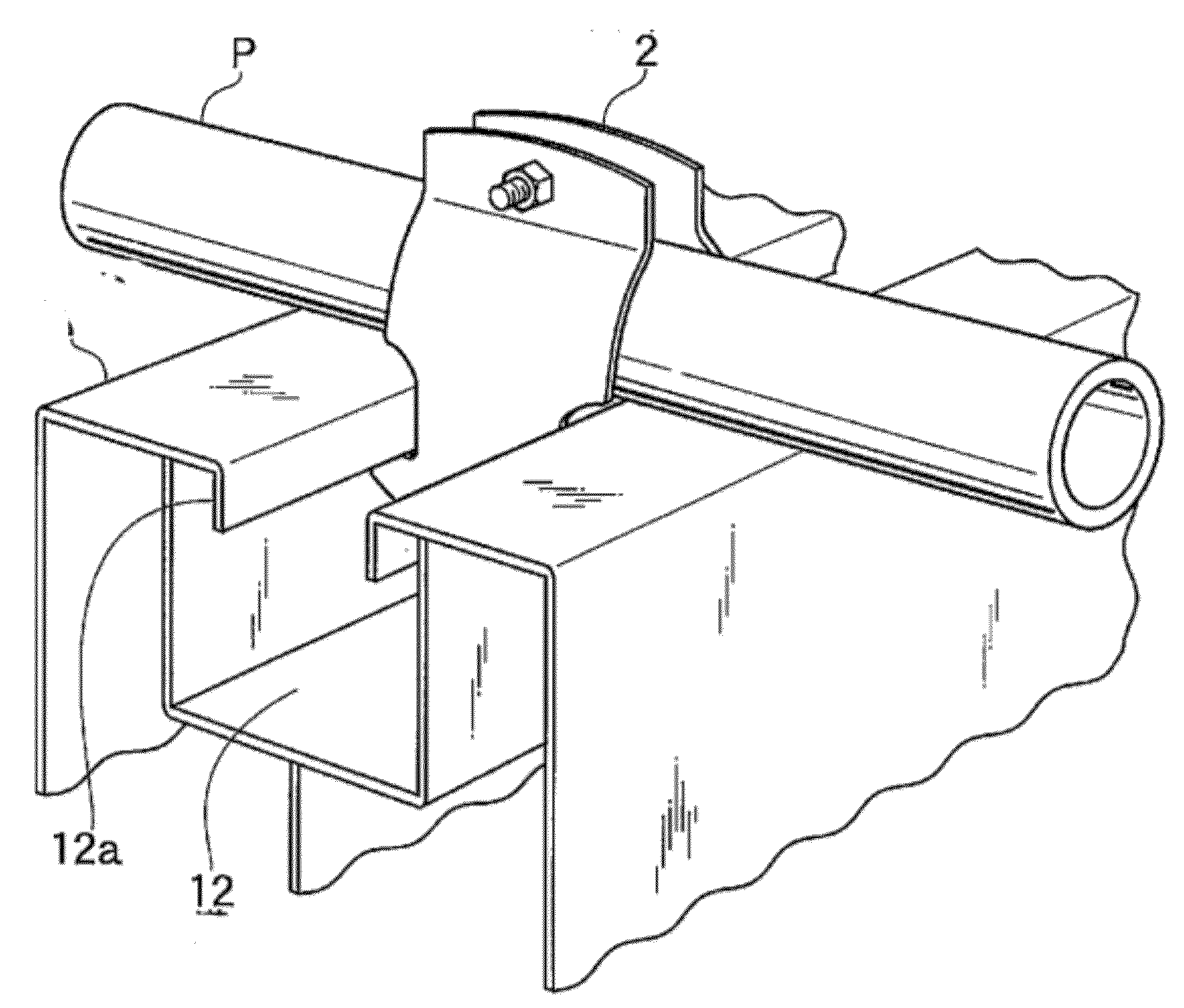
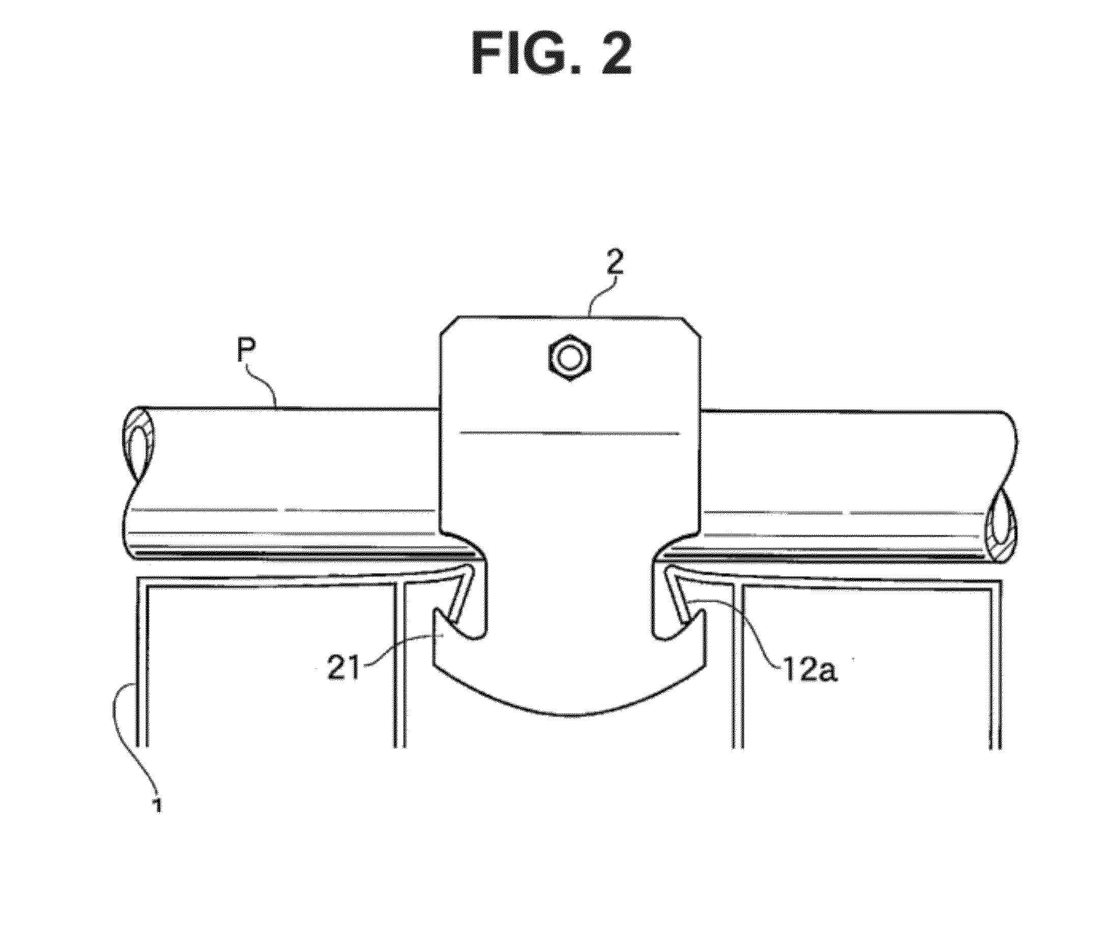
[0033]A groove 12 parallel to a through passage 13 is formed on any surface of the rectangular cylindrical body constituting pipe support base 1. An engagement plate 12a projecting in an eave shape toward the inside the cross section of groove 12 is then formed on the edge of groove 12. This...


PUM


Abstract

To provide a pipe support base light in weight and with good workability, to which loads may given according to need. This problem may be overcome with a hollow cylindrical body with a rectangular cross section and with four sides. A through passage is provided in the center portion thereof. Further, a cross-shaped rib is provided at an approximately central position thereof. Additionally, grooves are formed parallel to the aforementioned through passage on at least any of the surfaces, upon the edges of which are provided engagement plates protruding into the cross sections of the grooves.

Description

CROSS-REFERENCE TO RELATED APPLICATION(S) AND CLAIM OF PRIORITY[0001]This is a National Phase Application in the United States of International Application No. PCT / JP2009 / 003182 filed on Jul. 8, 2009. The entire disclosure of the above patent application is incorporated herein by reference.FIELD OF INVENTION[0002]This invention relates to a mounting for supporting various types of piping installed on building roofs or the like.BACKGROUND OF THE INVENTION[0003]Water supply tanks are normally arranged with cooling-heating devices on building roofs. In order to supply water and / or gas to the inside of a building from such tanks and devices, piping must be installed upon the roofs of these buildings.[0004]This piping is lifted a specific distance from the surface of a roof and is not fixed directly to the roof out of consideration for waterproofing. As such, structures have generally been used in which piping is supported by wood blocks, concrete blocks, or steel columns serving as a mo...

Claims


Application Information

Patent Timeline
Patent Type & Authority Applications(United States)
IPC IPC(8): F16L3/08
CPCF16L3/24F16L3/04F16L3/243
Inventor AZUMA, MASATOSHIHIKOYHAMA, ATSUSHI
Owner ADVANCE CO LTD
Why Eureka
Try Eureka