Rotor for a turbo generator, and turbo generator comprising a rotor

a turbo generator and rotor technology, which is applied in the direction of dynamo-electric machines, magnetic circuit rotating parts, magnetic circuit shapes/forms/construction, etc., can solve the problem of not being able to arbitrarily increase the power of the fan impeller seated on the rotor shaft, and achieve the effect of maximizing the length of the connecting duct, good cooling effect, and keeping the flow path of cooling gas as shor

Inactive Publication Date: 2012-05-17
SIEMENS AG
View PDF5 Cites 7 Cited by
  • Summary
  • Abstract
  • Description
  • Claims
  • Application Information

AI Technical Summary

Benefits of technology

[0017]One distribution duct can be assigned jointly to a plurality of feeding ducts. However, it is expedient to provide a central distribution duct for supplying all the feeding ducts with cooling gas. The formation of a central distribution duct makes it possible to maximize the length of the connecting ducts in the radial direction. As a result, the maximum achievable centrifugal force for the diameter of the rotor body acts on the cooling gas, thus enabling a particularly good cooling effect to be achieved.
[0018]In an expedient development, the at least one admission duct extends substantially in the radial direction. In this way, it is possible to keep the flow path of the cooling gas as short as possible. This is associated with a low flow resistance.
[0019]In an expedient development, the front ends of the feeding ducts are closed. As a result, it is not possible for unwanted leakage flows of cooling gas into the region of the two end windings arranged at the ends of the rotor body to occur. The cooling gas can thus be fed to the cooling ducts without loss.
[0020]In an expedient development, an additional conductor bar for the purpose of enlarging the excitation winding is arranged in the feeding duct, being matched to the dimensions of the latter. Additional windings of the excitation winding are thus formed by connecting adjacent additional conductor bars at the ends in the region of the two end windings by means of additional tangential conductors. It is thus possible in respect of the excitation winding to achieve an increased magnetic flux with a low outlay. It is thus possible to achieve an increased electric power for the turbo generator without major structural outlay.

Problems solved by technology

However, it is not possible to arbitrarily increase the power of the fan impellers seated on the rotor shaft since it is coupled to the speed of rotation of the rotor shaft.

Method used


Image

  • Rotor for a turbo generator, and turbo generator comprising a rotor
  • Rotor for a turbo generator, and turbo generator comprising a rotor
  • Rotor for a turbo generator, and turbo generator comprising a rotor

Examples


Embodiment Construction

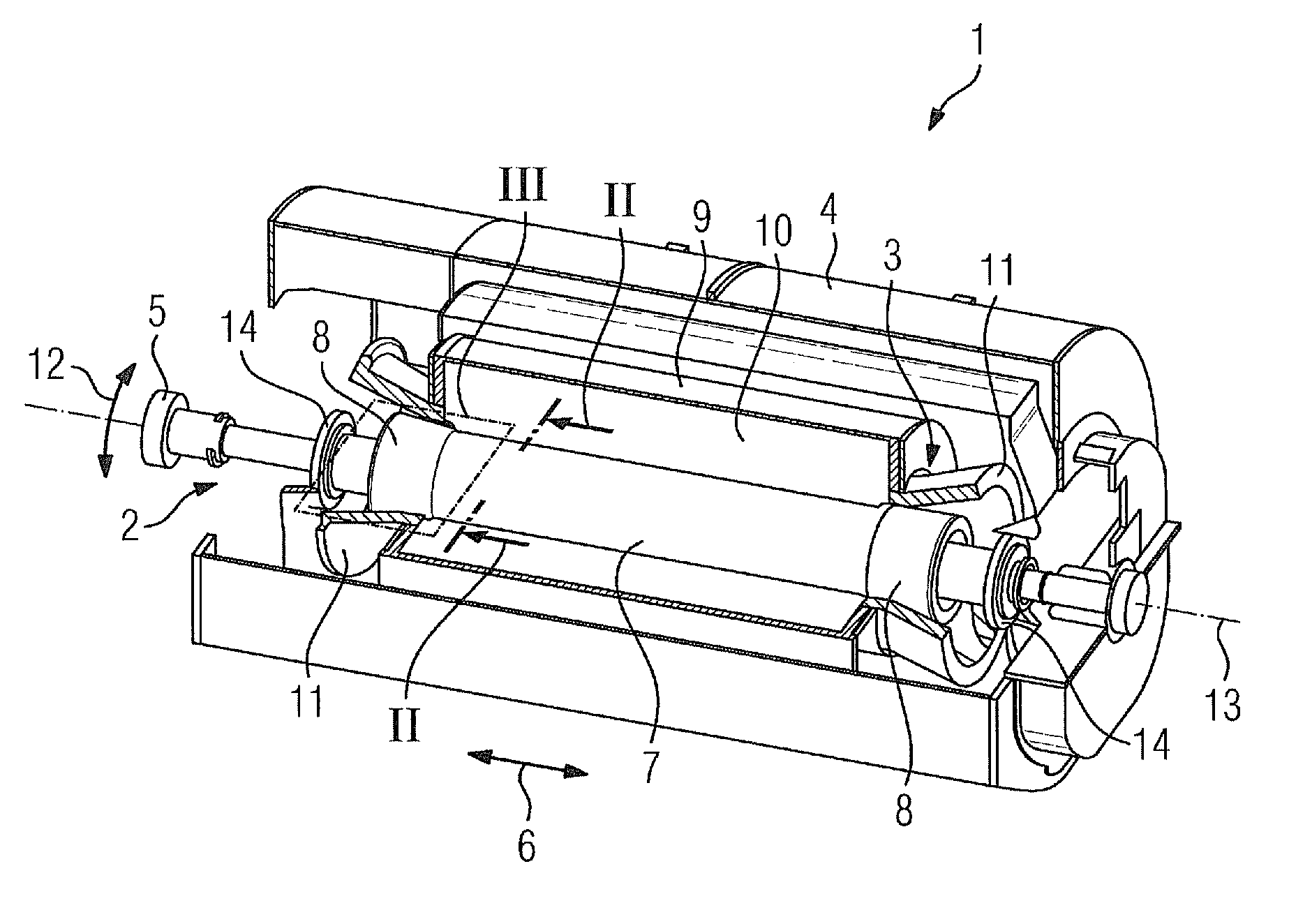
[0028]FIG. 1 shows a turbo generator 1 having a rotor 2 and a stator 3 accommodating the rotor. The rotor 2 is also referred to as a runner, and the stator 3 is also referred to as a stationary part or stationary component. The rotor 2 and the stator 3 are accommodated by a common gastight housing 4. The rotor 2 comprises a rotor shaft 5 that thickens in the center in the longitudinal direction 6 of the shaft to form a rotor body 7. The rotor body 7 is also referred to as a runner body or as an active component. An excitation winding (not shown in the figure) is arranged on the cylindrical surface of the rotor body 7. The two ends of the rotor body 7 as seen in the longitudinal direction 6 of the shaft each have a rotor cap 8. That section of the stator 3 which surrounds the rotor body 7 as seen in the longitudinal direction 6 of the shaft is referred to as the active component 9 of the stator or active component of the stationary part. The active component 9 of the stator has a fer...


PUM


Abstract

A rotor for a turbo generator is provided. The rotor includes a cylindrical rotor shaft that expands in the center to form a rotor body, grooves introduced into the cylindrical surface of the rotor body, an excitation winding accommodated in the grooves, a feeding duct through which a cooling gas flows, and cooling ducts which penetrate the excitation winding substantially in the radial direction and connect the feeding duct to respective outlets in the cylindrical surface of the rotor body A distribution duct extending in the longitudinal direction of the shaft is arranged in the area of the central longitudinal axis. The feeding ducts are connected to the distribution duct via junction ducts. An admission duct for feeding the cooling gas is provided for each distribution duct.

Description

CROSS REFERENCE TO RELATED APPLICATIONS[0001]This application is the US National Stage of International Application No. PCT / EP2010 / 052277, filed Feb. 23, 2010 and claims the benefit thereof. The International Application claims the benefits of European Patent Office application No. 09003400. EP filed Mar. 9, 2009. All of the applications are incorporated by reference herein in their entirety.FIELD OF INVENTION[0002]The invention relates to a rotor for a turbo generator and to a turbo generator comprising a rotor of this kind.BACKGROUND OF INVENTION[0003]A turbo generator is known from EP 1 742 330 A1, for example. It has a drivable, rotatably mounted rotor, also referred to as a runner, and a fixed stator surrounding the rotor, also referred to as a stationary component. The rotor comprises a cylindrical rotor shaft that thickens in the center in the longitudinal direction of the shaft to form a rotor body. The rotor body is also referred to as a runner body. An excitation winding, ...

Claims


Application Information

Patent Timeline
Patent Type & Authority Applications(United States)
IPC IPC(8): H02K9/00
CPCH02K1/32H02K9/08H02K3/24
Inventor KOWALSKI, WALDEMARLEHMANN, CHRISTOPH
Owner SIEMENS AG
Why Eureka
Try Eureka