

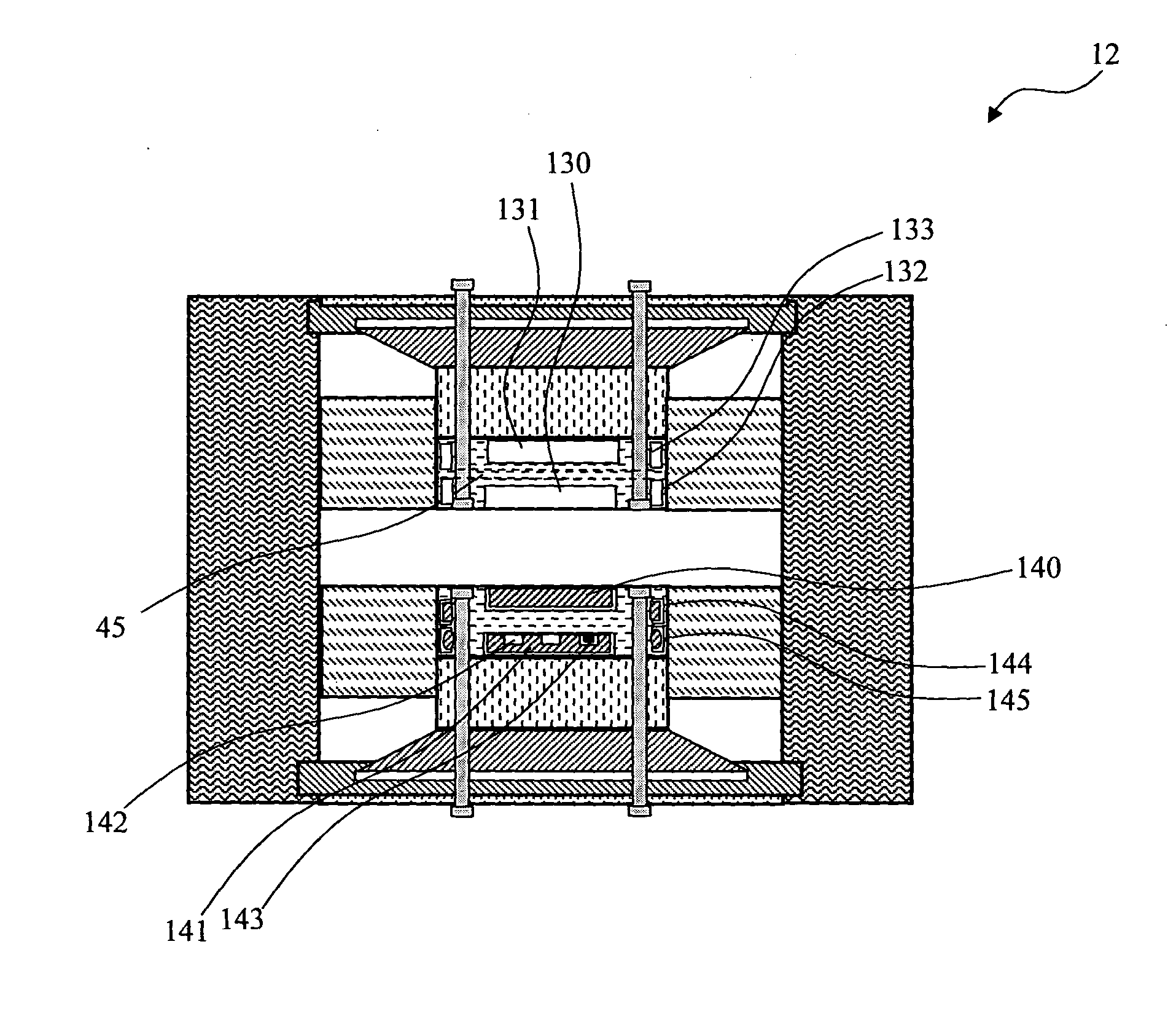
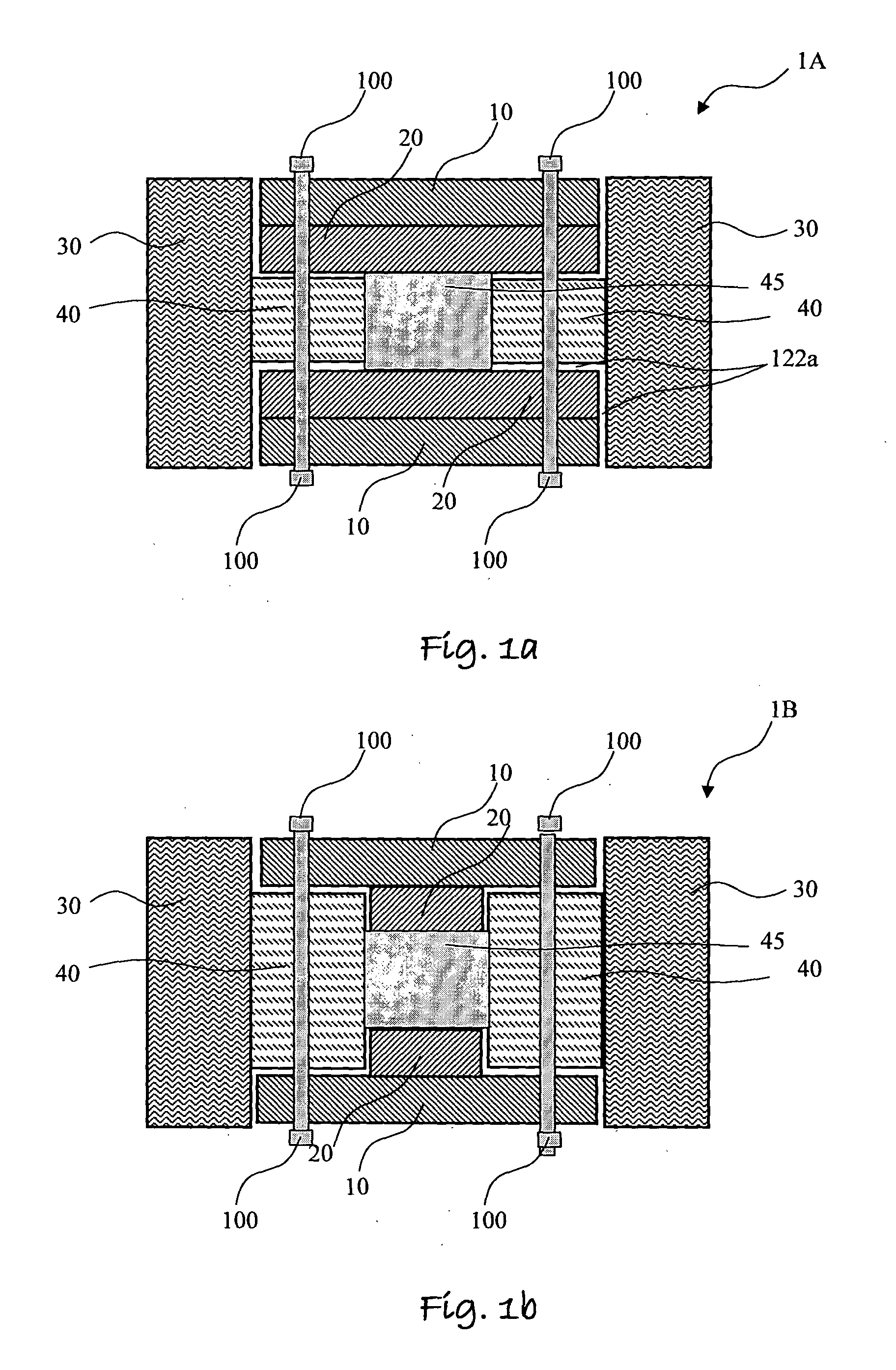
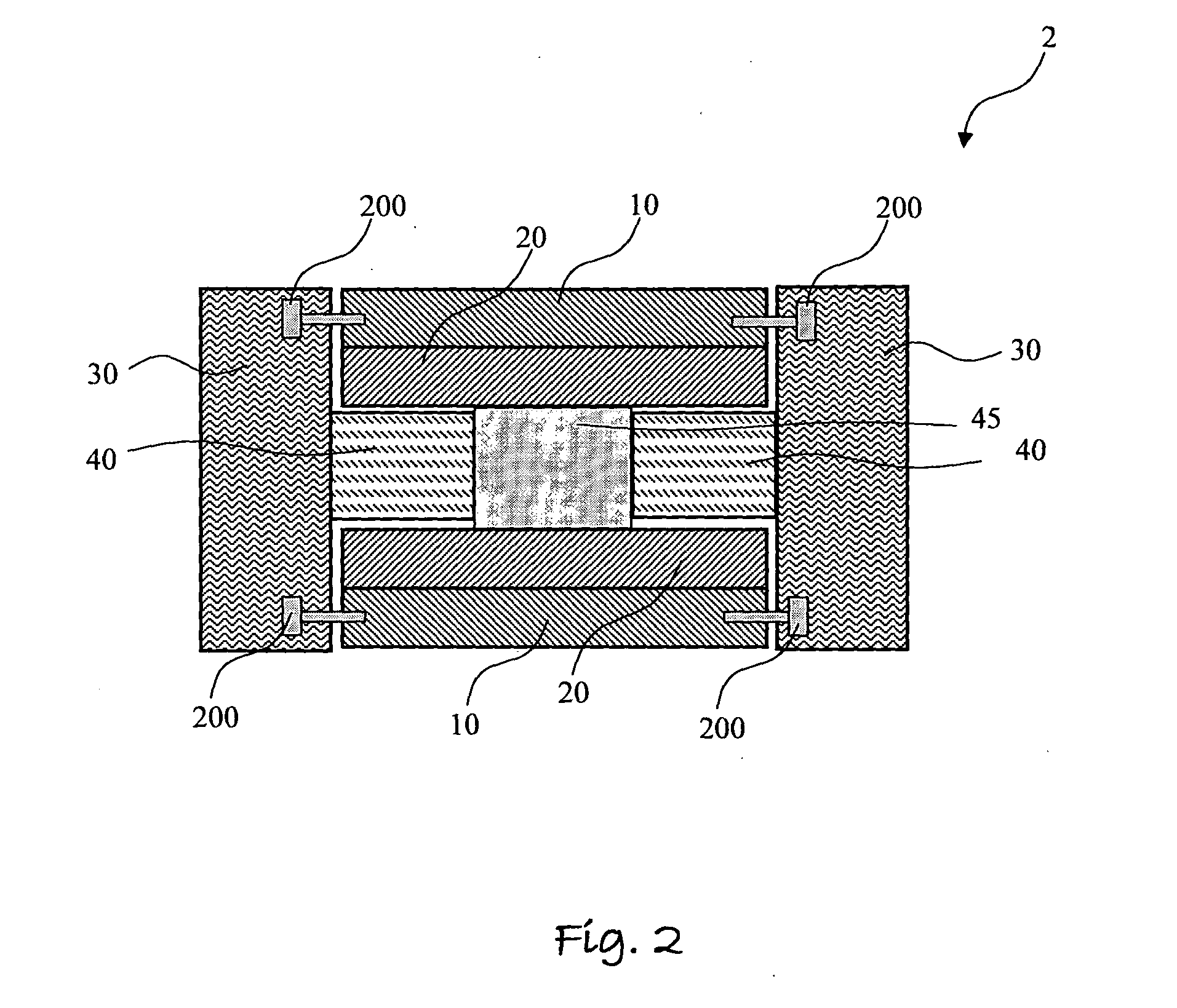
Cage in an mrd with a fastening/attenuating system
a magnetic resonance device and fastening technology, applied in the direction of reradiation, measurement using nmr, instruments, etc., can solve the problem that the use of simple permanent magnet structures, such as c-magnet and h-magnet configurations, is not enough to achieve a sufficiently uniform magnetic field, and achieve the effect of high homogeneous magnetic gradien
- Summary
- Abstract
- Description
- Claims
- Application Information
AI Technical Summary
Benefits of technology
Problems solved by technology
Method used
Image

Examples
Embodiment Construction
[0041]The following description is provided so as to enable any person skilled in the art to make use of the invention and sets forth the best modes contemplated by the inventor of carrying out this invention. Various modifications, however, will remain apparent to those skilled in the art, since the general principles of the present invention have been defined specifically to provide a cage in an MRD with a fastening / attenuating system and methods thereof. Therefore, the invention is not limited by that which is illustrated in the figures and described in the specification, but only as indicated in the accompanying claims, with the proper scope determined only by the broadest interpretation of said claims.
[0042]The term ‘magnetic resonance device’ (MRD) applies hereinafter to any Magnetic Resonance Imaging (MRI) device, any Nuclear Magnetic Resonance (NMR) spectroscope, any Electron Spin Resonance (ESR) spectroscope, any Nuclear Quadrupole Resonance (NQR) or any combination thereof...
PUM
| Property | Measurement | Unit |
|---|---|---|
| circumference | aaaaa | aaaaa |
| shape | aaaaa | aaaaa |
| homogeneous magnetic | aaaaa | aaaaa |
Abstract
Description
Claims
Application Information