Receive timing manager

a timing manager and data technology, applied in the field of digital circuits, can solve the problems of inability to detect data, insufficient setup time, data receiving logic, etc., and achieve the effect of improving data-receiving speed, reducing accuracy requirements, and improving data-receiving speed

Active Publication Date: 2012-05-17
TEXAS INSTR INC
View PDF7 Cites 0 Cited by
  • Summary
  • Abstract
  • Description
  • Claims
  • Application Information

AI Technical Summary

Benefits of technology

[0011]In one aspect of the present invention, data-receiving speed is improved by using a small sample window. A sample window is made smaller than the system clock period. Multiple samples are taken. Data transition points are found by using an edge detector. An optimal sample point is selected away from the transition points. The transition points may be found inside the sample window, the optimal sample point will be a point away from the transition point. The temperature variation and voltage variation may cause the transition point to move, and the optimal sample will be moved also to stay away from the transition point. If the transition point is outside the sample window, a default optimal sample point is pre-selected in the sample window. The pre-selected optimal sample point is used until the transition point moves into the sample window, at which time the optimal sample point moves also. The small sample widow is suitable for low speed data transfer such as single data rate (SDR) with lower accuracy requirement.
[0012]In another aspect of the present invention, data-receiving speed is improved by using a big sample window. A sample window is made greater than the system clock period, preferably greater than one and half the system clock period. Rising edges and falling edges of the system clock are found. Transition points are found and the optimal sample points are selected at certain points related to the interval between the rising / falling and falling / rising edges. The samples may be across the clock boundary so that the data dragging technique is used to return the sampled data back to the system clock. The sample is re-sampled at a point of the next clock cycle before it is re-sampled at a system clock, where the re-sample point is smaller than the sample point of the original sample. In one preferred embodiment, the re-sample point is half the sample point of the original sample. Dragging samples creates a window larger than the clock period so that the variation can be greater than a clock period just less than two clocks. The bigger sample window is primarily used for higher speed data transfer, such as double data rate (DDR).
[0013]The preferred embodiment of the present invention eliminated the greatest variation, the process variation among the three common variations. Also by re-sampling the data, the setup and hold time can be guaranteed. Therefore, higher speed data transfer can be achieved with the existing devices.

Problems solved by technology

The data receiving logic, however, cannot detect data right at the time the transition occurs since the data is not yet stable and errors can occur even if the data is detected not at but very close to the data transition point.
If the setup time TSU is too close to the system clock time 7, there is no adequate setup time.
A significant limitation of a non-PLL based design is that its speed is limited by the round trip latency time of the system.
If the IO delay is large, or the remote system is an old and slow system, the round trip latency time will be big so that the system speed will be significantly limited.
This method solves the round trip latency issues, but incurs other costs.
3) Another disadvantage of a PLL is that a FIFO (First in First out buffer) is needed.
Therefore the system becomes more complicated.
The extra FIFO not only increases the cost, it also increases the design complexity.
With the above-discussed limitations of the PLL and non-PLL based designs, the system's data receiving speed is greatly limited.

Method used


Image

  • Receive timing manager
  • Receive timing manager
  • Receive timing manager

Examples


Embodiment Construction

[0027]The making and using of the presently preferred embodiments are discussed in detail below. It should be appreciated, however, that the present invention provides many applicable inventive concepts that can be embodied in a wide variety of specific contexts. The specific embodiments discussed are merely illustrative of specific ways to make and use the invention, and do not limit the scope of the invention.

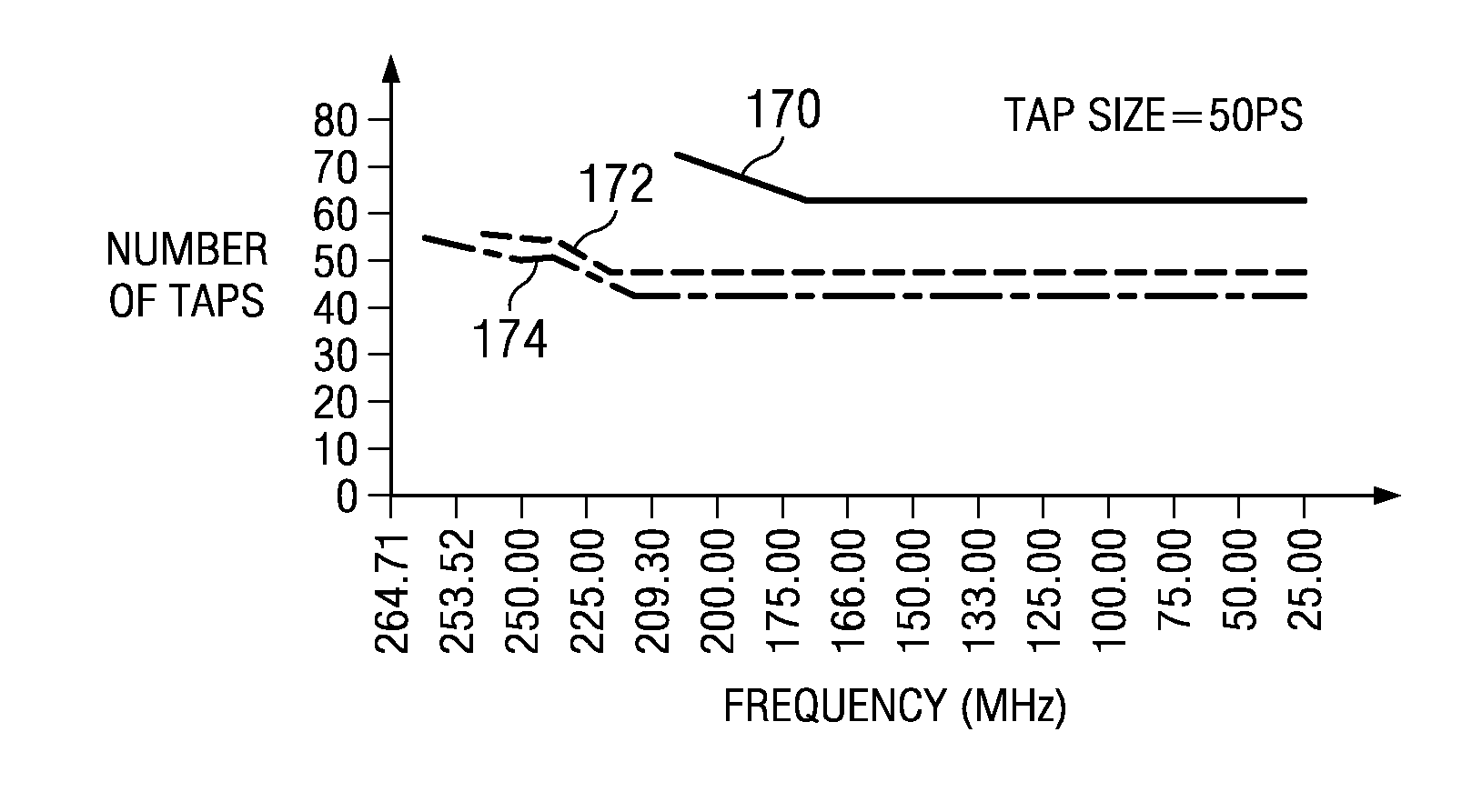
[0028]The preferred embodiments of a receive timing manager are discussed. Receive timing manager (RTM) is a serial receive logic circuit used, for example, to assist in meeting receive data setup and hold timing. In this case, an RTM is a digitally developed apparatus to emulate a PLL. The RTM can sample multiple samples, and use a methodology to decide the optimal sampling time. An RTM responds quickly to the time variations. It can also drag the data back to the main clock so that the setup and hold time requirement can be met. It makes use of a fact that the data received...


PUM


Abstract

A novel receive timing manager is presented. The preferred embodiment of the present invention comprises an edge detection logic to detect the data transition points, a plurality of data flip-flops for storing data at different sample points, and a multiplexer to select the ideal sample point based on the transition points found. A sample window is made with multiple samples. The sample window size can be designed smaller or greater than the system clock period based on the data transfer speed and accuracy requirement.

Description

CROSS-REFERENCE TO RELATED APPLICATIONS[0001]This application is a divisional of U.S. patent application Ser. No. 11 / 098,130, filed Apr. 4, 2005, which is incorporated herein by reference in its entirety.TECHNICAL FIELD[0002]This invention relates generally to digital circuits, and more specifically to the timing of receiving data.BACKGROUND[0003]A phase-locked loop (PLL) is a closed loop frequency control system. Its function is based on the phase sensitive detection of a phase difference between the input and output signals of a voltage controlled oscillator (VCO). They can be configured as frequency multipliers, demodulators, tracking generators or clock recovery circuits. PLLs are widely used in modern circuit design, especially in communication system design.[0004]When data comes in, the data is reflected as logic highs or logic lows. The data receiving logic detects the logic highs or logic lows and therefore decides what the data is. When the data changes from a logic high or...

Claims


Application Information

Patent Timeline
Patent Type & Authority Applications(United States)
IPC IPC(8): H04L7/033H03L7/00
CPCH04L7/0338
Inventor BEAUDOIN, DENIS ROLANDSOJITRA, RITESH DHIRAJLALCHRISTISON, GREGORY LEE
Owner TEXAS INSTR INC
Why Eureka
Try Eureka