
Multistage dry vacuum pump

a vacuum pump and multi-stage technology, applied in the direction of pump, positive displacement liquid engine, liquid fuel engine, etc., can solve the problems of long time to reach a desired vacuum degree, inability to achieve high vacuum level, and inability to achieve desired vacuum degree, etc., to achieve the effect of increasing exhaust pressure, saving manufacturing cost at lot, and reducing the size of the pump apparatus

Active Publication Date: 2012-05-17
KIM DAVID
View PDF4 Cites 10 Cited by
  • Summary
  • Abstract
  • Description
  • Claims
  • Application Information

AI Technical Summary

Benefits of technology

[0013]The multistage dry vacuum pump according to the present invention has the following advantages.
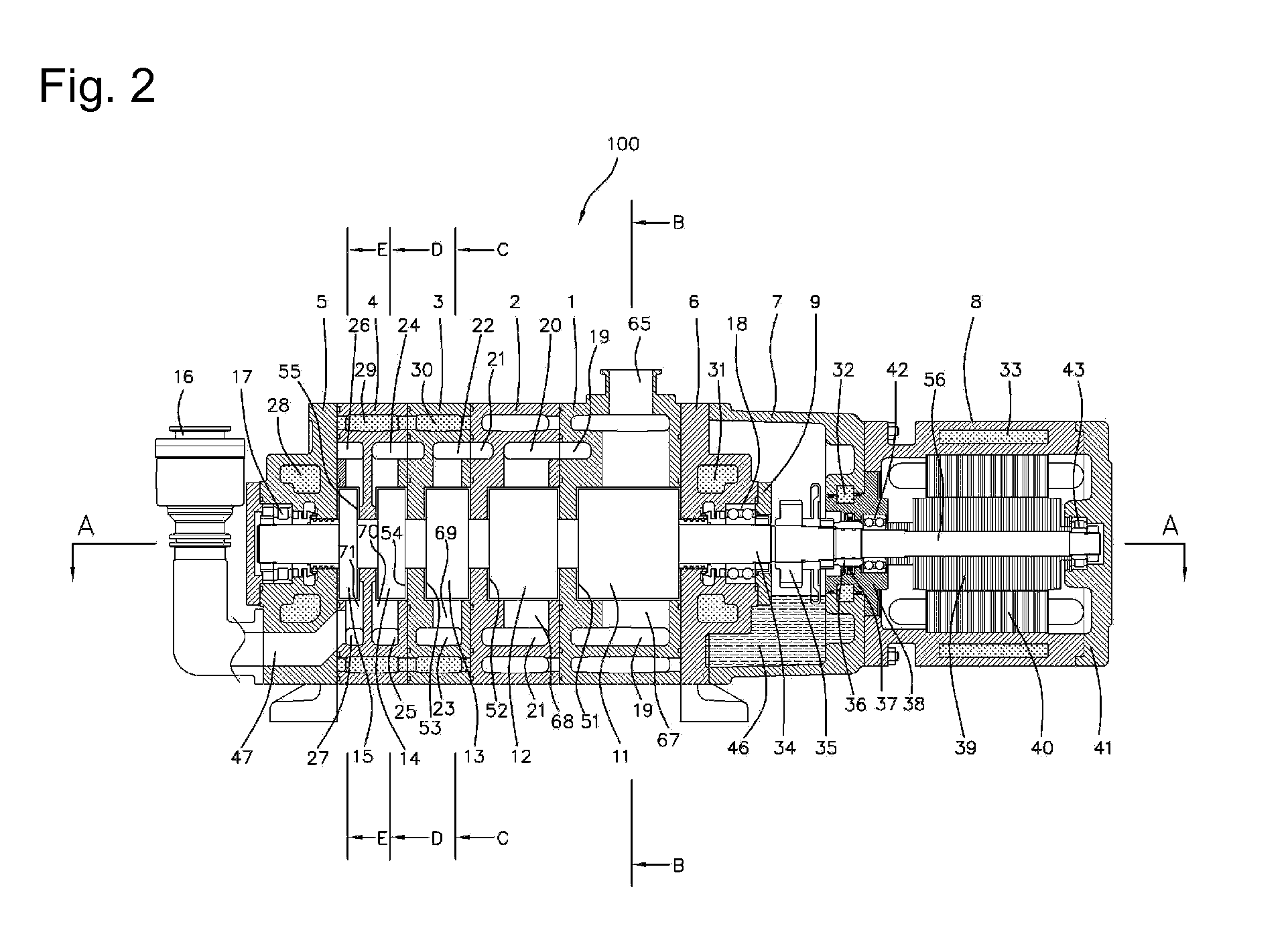
[0014]1) The present invention is directed to concurrently cooling the multistage cylinder body of the pump apparatus and the rotors of the cylinder, in which a gas passage is formed in the cylinder body in a shape of surrounding the outer side of each cylinder, and a cooling water jacket is formed surrounding the outer side of the gas passages, and the cooling water circulates in each cooling water jacket for thereby cooling the gas passing through the gas passage based on a heat exchange method, and the cooled gas concurrently cools the cylinder body and the rotor for thereby making the cylinder body and the rotors have similar temperatures for thereby minimizing the differences of the thermal expansions between elements, so it is possible to make the gap between the rotor and the inner diameter of the cylinder and between a pair of the rotors smaller. For example, it is possible to obtain 10−3 Torr of vacuum degree by installing a five-stage cylinder structure, whereas the conventional pump apparatus can obtain 10−3 Torr of vacuum degree by connecting two pump apparatus of a three-stage cylinder structure in series. The present invention can obtain the performance by using one pump apparatus which can be obtained by two pump apparatus in the conventional art, so the size of the pump apparatus can be made smaller, while saving manufacturing cost at lot.
[0015]2) Part of the gas cooled via a communication passage connecting the gas passage of the cylinder body and the exhaust space of the cylinder is fed back to the cylinder for thereby increasing exhaust pressure while promoting the discharge of gas, which results in enhancing a reach vacuum degree and exhaust speed while concurrently cooling the cylinder body and the rotor. So, it is possible to make a stable pump environment with the aid of similar thermal expansion conditions between elements.
[0016]3) The cooling water jackets are formed at the front cover, the rear cover, the sealing housing and the driving motor, respectively, so the cooling water circulating in each water jacket during the operation of the pump apparatus cools the heat from the bearing, gear, lubricant oil, shaft seal oil and motor for thereby enhancing the life spans of parts.
[0017]4) The size of the pump can be reduced by directly connecting the driving motor to the pump for thereby significantly reducing the installation space and saving manufacturing cost by reducing the number of parts.
[0018]5) The cylinders can be made in a three-stage structure, a four-stage structure or a five-stage structure depending on the reach vacuum degree of the pump apparatus. The parts made via the same manufacturing process can be applied to various models of products, which lead to saving manufacturing cost, and it is possible to select a desired pump apparatus depending on a needed vacuum degree.
[0019]6) The cylinder body of the last stage contacting with the rear cover is equipped with two cylinders for thereby saving manufacturing cost by decreasing the number of parts.

Problems solved by technology

In this case, a high vacuum level cannot be easily obtained due to the bigger gaps or since an exhaust speed is lowered, it takes long time to reach a desired vacuum degree or it becomes impossible to reach a desired vacuum degree.
Since it is impossible to control overheating of a rotor, the pump might be adhesively stuck in the course of operation by means of an over thermal expansion of the rotor as compared to the cylinder.
Two pumps are connected without considering connecting more pumps in a multistage pump structure for the reasons that when the pump structure is made in at least three pump structure, an overheating problem due to the increase in the compression ratios and the difference of the thermal expansion of each member cannot be overcome.
In this case, connecting two three-stage pumps leads to a long passage of working gas, and the prices of the pumps and maintenance cost significantly increase (about two times maintenance costs are needed when installing two pumps as compared to one pump).

Method used


Image

  • Multistage dry vacuum pump
  • Multistage dry vacuum pump
  • Multistage dry vacuum pump

Examples


Embodiment Construction

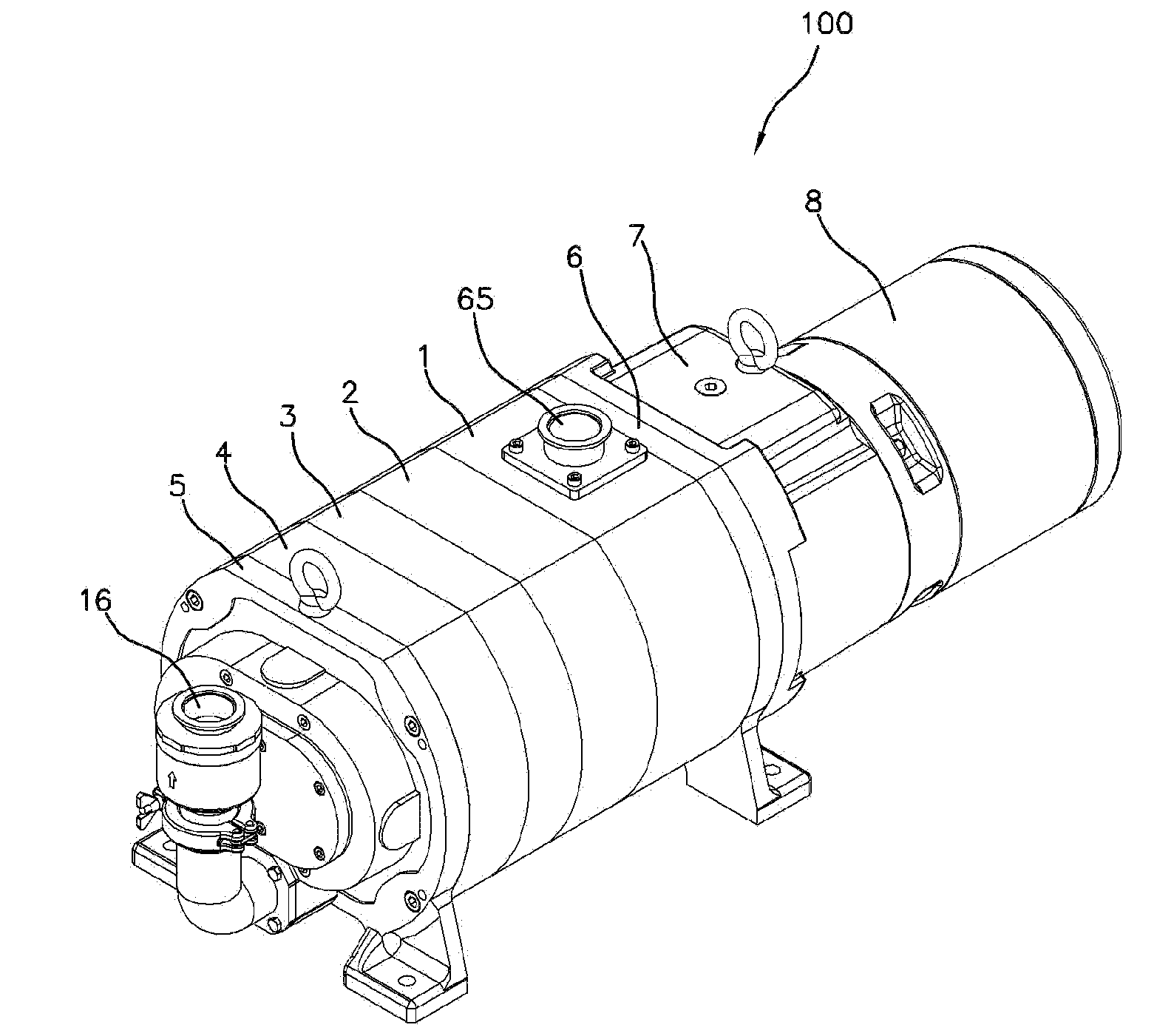
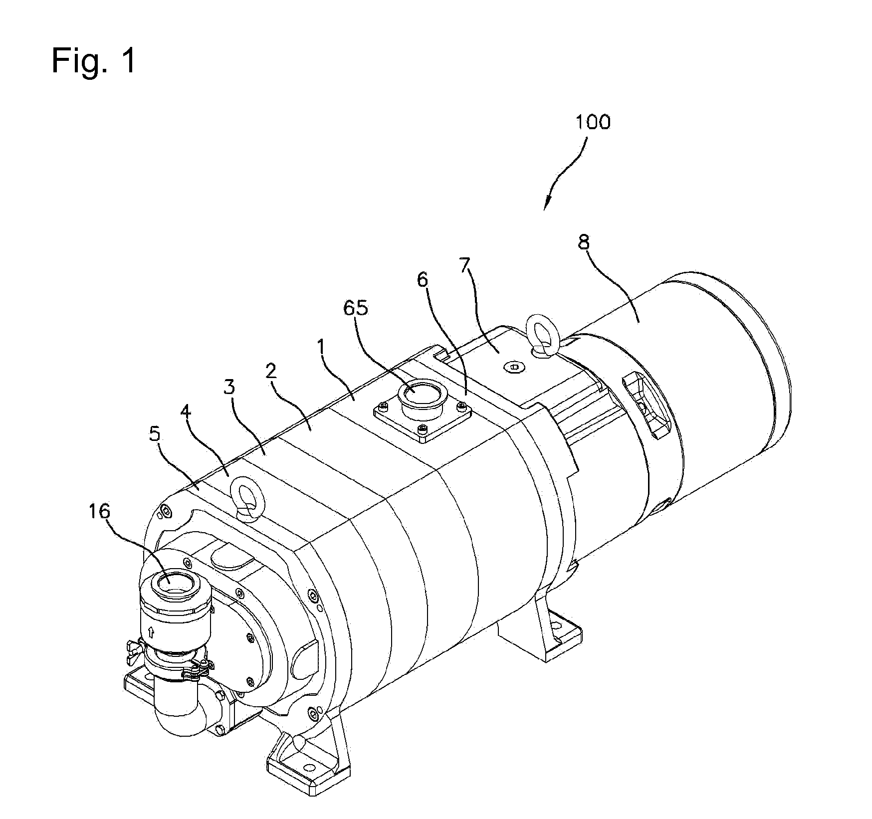
[0027]The present invention can be implemented in detailed with the following embodiments. Such embodiments are provided for only illustrative purpose to an extent that those skilled in the art can implement, not limiting the scope of the claims of the present invention. So, the present invention is not limited to the embodiments to be descried, and it is obvious that any part or modification obtained as a result of the present invention will belong to the present invention. The preferred embodiments of the present invention will be described with reference to the accompanying drawings. The multistage dry vacuum pump will be described in details.

[0028]As shown in FIGS. 1 through 3, the vacuum pump apparatus 100 according to the present invention comprises a multistage cylinder body formed of a 2-stage through 6-stage, preferably, 3-stage through 5-stage. In the preferred embodiment of the present invention, there are provided four cylinder bodies 1, 2, 3 and 4 (cylinder blocks) arra...


PUM


Abstract

The multistage dry vacuum pump is disclosed, in which it is possible to prevent a pump from being adhesively stuck, which problem occurs due to a difference in thermal expansions between a cylinder body and a rotor, by making thermal expansion conditions between a cylinder body and a rotor of a pump similar by concurrently cooling the cylinder body and the rotor of the pump, and a high vacuum degree can be obtained by obtaining an optimum gap design in the rotor and the cylinder, respectively, for thereby making the size of the pump smaller and significantly reducing the maintenance cost of the pump facilities. The gas passage for transferring gas compressed by each cylinder is provided at each cylinder body in a shape of surrounding an outer side of each cylinder, and a cooling water jacket for circulating cooling water is provided close to an outer side of the gas passage, and a communication passage is formed at a gas passage contacting with the cooling water jacket and is connected with an exhaust pace of the cylinder.

Description

TECHNICAL FIELD[0001]The present invention relates to a multistage dry vacuum pump, and in particular to a multistage dry vacuum pump in which a gas passage is formed coming into contact with an outer wall of a cylinder of a pump body, and cooling water is forced to circulate around an outer wall of the gas passage, and the gas passage communicates with an exhaust space of the cylinder, so the gas cooled in the gas passage is cooled together with the cylinder body and a rotor for thereby making the cylinder body and the rotor operate under an environment of similar temperatures and thermal expansion.BACKGROUND ART[0002]A conventional vacuum pump cooling technology is implemented in a structure that a cylinder body is directly cooled by forming a cooling water passage at an outer wall of a pump body cylinder, so a high temperate heat generating during a compress process in which a rotor intakes and exhausts into the interior of a cylinder is directly transferred to a rotor and is hea...

Claims


Application Information

Patent Timeline
Patent Type & Authority Applications(United States)
IPC IPC(8): F04B25/00
CPCF01C21/10F04C18/126F04C23/001F04C2240/30F04C28/02F04C29/04F04C29/12F04C25/02
Inventor KIM, DAVID
Owner KIM DAVID
Learn More