Laser processing apparatus and container manufacturing apparatus

Active Publication Date: 2012-05-17
NIPPON STEEL CORP
View PDF5 Cites 5 Cited by
  • Summary
  • Abstract
  • Description
  • Claims
  • Application Information

AI Technical Summary

Benefits of technology

[0031]According to the present invention, part of a laser beam irradiated to an end portion of a cylinder can be irradiated to another end portion again. Therefore, it is possible to irradiate the laser beam highly efficiently to the end portion of the cylinder. Therefore, when the cylinder has resin films formed on its inner surface and outer surface, it is possible to remove the resin films with using the laser beam highly efficiently.

Problems solved by technology

The resin hairs, though harmless to human bodies, are suspected as an unsanitary matter by consumers when mixed in the can, which can be a target of complaint.
However, the art described in Patent Literature 5 is not capable of sufficiently preventing the generation of the resin hairs.
Further, according to the art described in Patent Literature 6 or 7, though the desired object is attained, its efficiency cannot be said to be high because an amount of the resin films that can be removed is not large, considering an energy amount required for the irradiation of the laser beam.

Method used


Image

  • Laser processing apparatus and container manufacturing apparatus
  • Laser processing apparatus and container manufacturing apparatus
  • Laser processing apparatus and container manufacturing apparatus

Examples


first embodiment

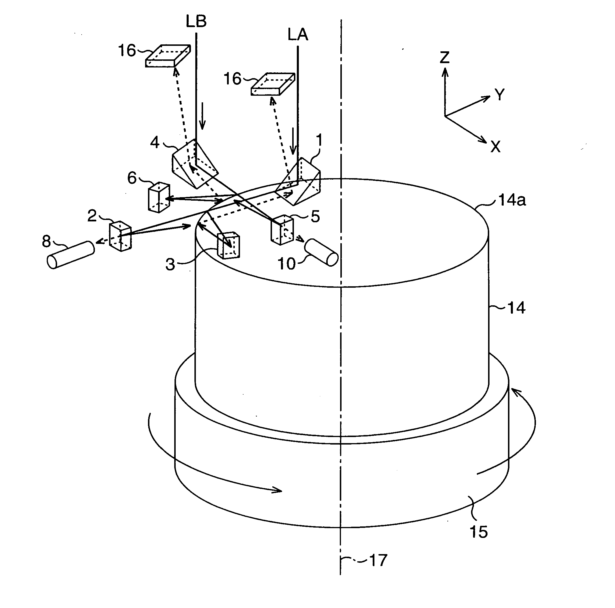
[0062]First, a first embodiment will be described. FIG. 3 is a view illustrating a laser processing apparatus (container manufacturing apparatus) according to the first embodiment of the present invention, and is a perspective view thereof seen from a diagonally upper side of a cup 14 being a material to be processed. Further, FIG. 4A is a plane view seen from an upper side of the cup 14, FIG. 4B is an enlarged plane view illustrating irradiation target portions to which laser beams LA and LB are irradiated, at an upper edge portion 14a of the cup 14, and FIG. 4C is an enlarged side view illustrating the irradiation target portions. Note that as for the coordinates illustrated in FIG. 3 and FIG. 4A to FIG. 4C, a radius direction of the cup 14 is an X direction, a tangent direction of the cup 14 is a Y direction, and a rotation axis direction of the cup 14 is a Z direction.

[0063]In the first embodiment, a rotating pedestal 15 on which the cup 14 is fixed is provided as illustrated in...

second embodiment

[0080]Next, a second embodiment will be described. FIG. 5A is a plane view of a laser processing apparatus according to the second embodiment seen from an upper side of a cup 14, FIG. 5B is an enlarged plane view illustrating irradiation target portions irradiated with laser beams LA and LB at an upper edge portion 14a of the cup 14, and FIG. 5C is an enlarged side view illustrating the irradiation target portions.

[0081]In the second embodiment, as illustrated in FIG. 5A to FIG. 5C, a first reflection mirror 1, a second reflection mirror 2, a third reflection mirror 3, and a first' reflection mirror 4 are disposed and their reflection angles are adjusted so that the following relation is satisfied.

[0082](a) The laser beam LA is reflected by the first reflection mirror 1 to be guided to a first irradiation target portion A1.

[0083](b) The laser beam LB is reflected by the first' reflection mirror 4 to be guided to a first' irradiation target portion B1.

[0084](c) Part, of the laser bea...

third embodiment

[0091]Next, a third embodiment will be described. FIG. 6A is a plane view of a laser processing apparatus according to the third embodiment seen from an upper side of a cup 14, FIG. 6B is an enlarged plane view illustrating irradiation target portions irradiated with laser beams LA and LB at an upper edge portion 14a of the cup 14, and FIG. 6C is an enlarged side view illustrating the irradiation target portions.

[0092]In the third embodiment, as illustrated in FIG. 6A to FIG. 6C, a first reflection mirror 1, a second reflection mirror 2, and a third reflection mirror 3 are disposed in the same manner as in the first embodiment. There is further provided a fourth reflection mirror 7 further reflecting a laser beam LA reflected at a second irradiation target portion A2 to guide the laser beam LA to a fourth irradiation target portion A4 (outer surface). In the third embodiment, the fourth reflection mirror 7 corresponds to a sixth reflector. Further, a laser light-receiving element 10...


PUM

PropertyMeasurementUnit
Light intensityaaaaaaaaaa

Abstract

A laser processing apparatus includes: a reflection mirror (1, 4) reflecting a laser beam (LA, LB) to an inner or outer surface at an upper edge portion (14a) of a cup (14); a reflection mirror (2, 5) reflecting a part that has passed an outer side of the upper edge portion (14a), of the laser beam (LA, LB) reflected by the reflection mirror (1, 4), to an outer or inner surface of the cup (14); and a rotating pedestal (15) rotating the cup (14) around its center relative to the reflection mirror (1, 4) and the reflection mirror (2, 5).

Description

[0001]This application is a national stage application of International Application No. PCT / JP2010 / 062625, filed 27 Jul. 2010, which claims priority to Japanese Application No. 2009-174925 filed 28 Jul. 2009, which is incorporated by reference in its entirety.TECHNICAL FIELD[0002]The present invention relates to a laser processing apparatus and a container manufacturing apparatus suitable for preventing resin hairs from being generated when a cylindrical container is manufactured from a primary drawn material or the like of a metal plate having resin films on its both surfaces.BACKGROUND ART[0003]As a beverage can, a food can, and so on, there have conventionally been used containers (seamless cans) such as a drawn can (Patent Literature 1), a thinned redrawn can (Patent Literatures 2, 3), and a thinned redrawn-ironed can (for example, refer to Patent Literature 4). In the manufacture of these containers, a disk-shaped blank is first punched out from a plate material in which resin ...

Claims


Application Information

Patent Timeline
IPC IPC(8): B29B13/08B23K26/00B23K26/08B23K26/36
CPCB23K26/0823B23K26/362B23K2201/12B23K26/409B23K26/367B21D51/2615B23K26/40B23K26/361B23K26/364B23K2101/12B23K2103/172
Inventor SAKAI, TATSUHIKOYOKOYA, HIROKAZU
Owner NIPPON STEEL CORP
Why Eureka
Try Eureka