

Compact LED module and projection display adopting the same
- Summary
- Abstract
- Description
- Claims
- Application Information
AI Technical Summary
Benefits of technology
Problems solved by technology
Method used
Image

Examples
Embodiment Construction
[0038] Hereinafter, illustrative, non-limiting embodiments of the present invention will be described in detail with reference to the attached drawings. Like reference numerals refer to like elements throughout.
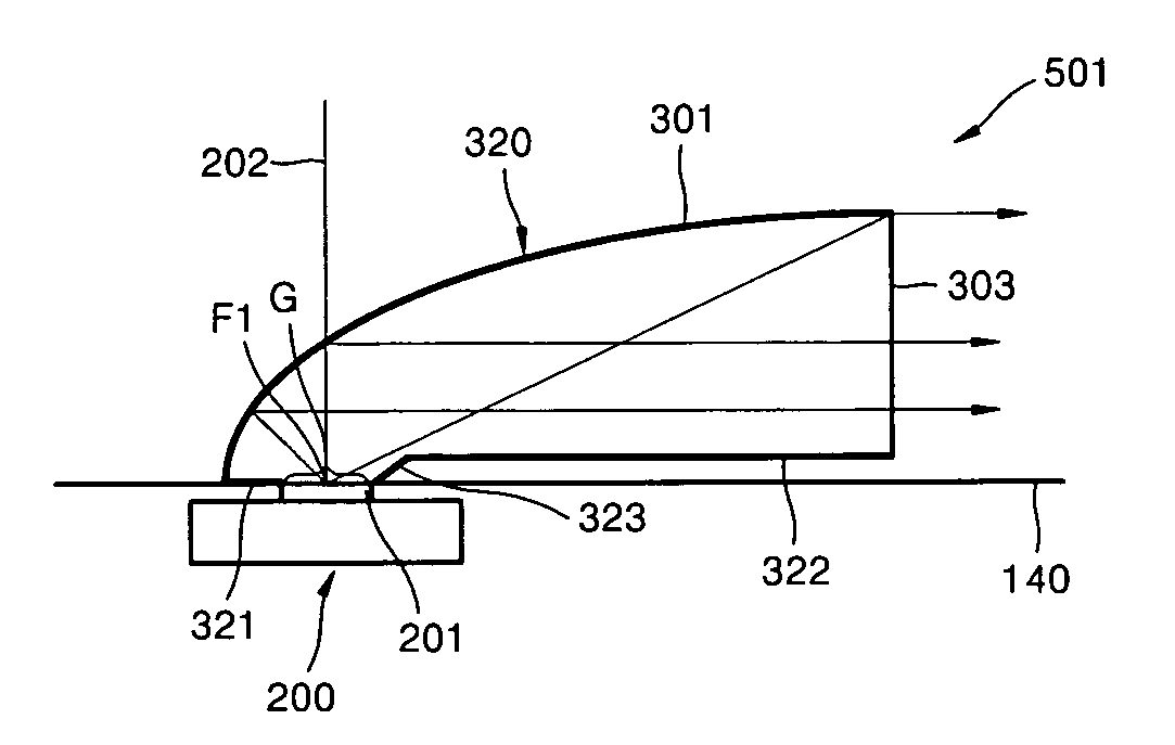
[0039]FIG. 5 is an exploded perspective view of a compact light source module, according to an embodiment of the present invention, and FIG. 6 is a cross-sectional view taken along line I-I′ of FIG. 5. Referring to FIGS. 5 and 6, an LED 200 is used as the compact light source. A collimator 101 is prepared on the LED 200. The LED 200 includes an LED chip 201 which emits a light beam. Although not shown, the LED 200 further includes a heat emitter which emits heat generated from the LED chip 201, and an anode and a cathode which supply the LED chip 201 with a current. In the present embodiment, the LED 200 does not include the dome lens 62 of FIG. 2. This does not limit the scope of the present invention. The structure of the LED 200 is well known to one of ordinary skill in t...
PUM
 Abstract
Description
Claims
Application Information