Light source apparatus and projector

a technology of light source and projector, which is applied in the direction of lighting and heating apparatus, instruments, spectral modifiers, etc., can solve the problems of inability to efficiently combine polarized light fluxes, and achieve the effect of suppressing the increase in the size of the light source and efficient combining light fluxes

Active Publication Date: 2014-01-30
SEIKO EPSON CORP
View PDF19 Cites 18 Cited by
  • Summary
  • Abstract
  • Description
  • Claims
  • Application Information

AI Technical Summary

Benefits of technology

[0006]An advantage of some aspects of the invention is to provide a light source apparatus capable of efficiently combining light fluxes from a light source having polarization dependence and a projector capable of forming high-intensity image light with an increase in size of the light source suppressed using the light source apparatus.

Problems solved by technology

In JP-A-2011-158502, however, for example, depending on the wavelength band of each of the light fluxes emitted from the light sources, the polarizer may not be capable of efficiently combining the polarized light fluxes due, for example, to a narrow polarization separation band corresponding to the area between the wavelength at which P-polarized light is transmitted at a transmittance of 50% and the wavelength at which S-polarized light is transmitted at a transmittance of 50%.

Method used


Image

  • Light source apparatus and projector
  • Light source apparatus and projector
  • Light source apparatus and projector

Examples


first embodiment

[0027]A light source apparatus according to a first embodiment of the invention will be described below in detail with reference to the drawings.

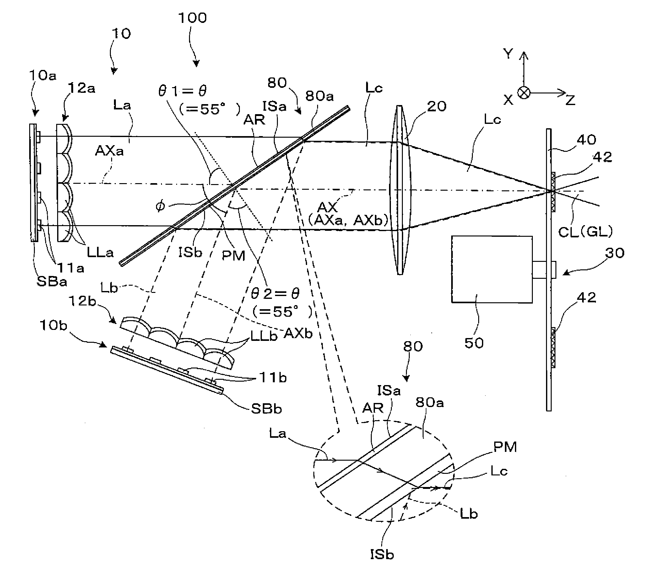
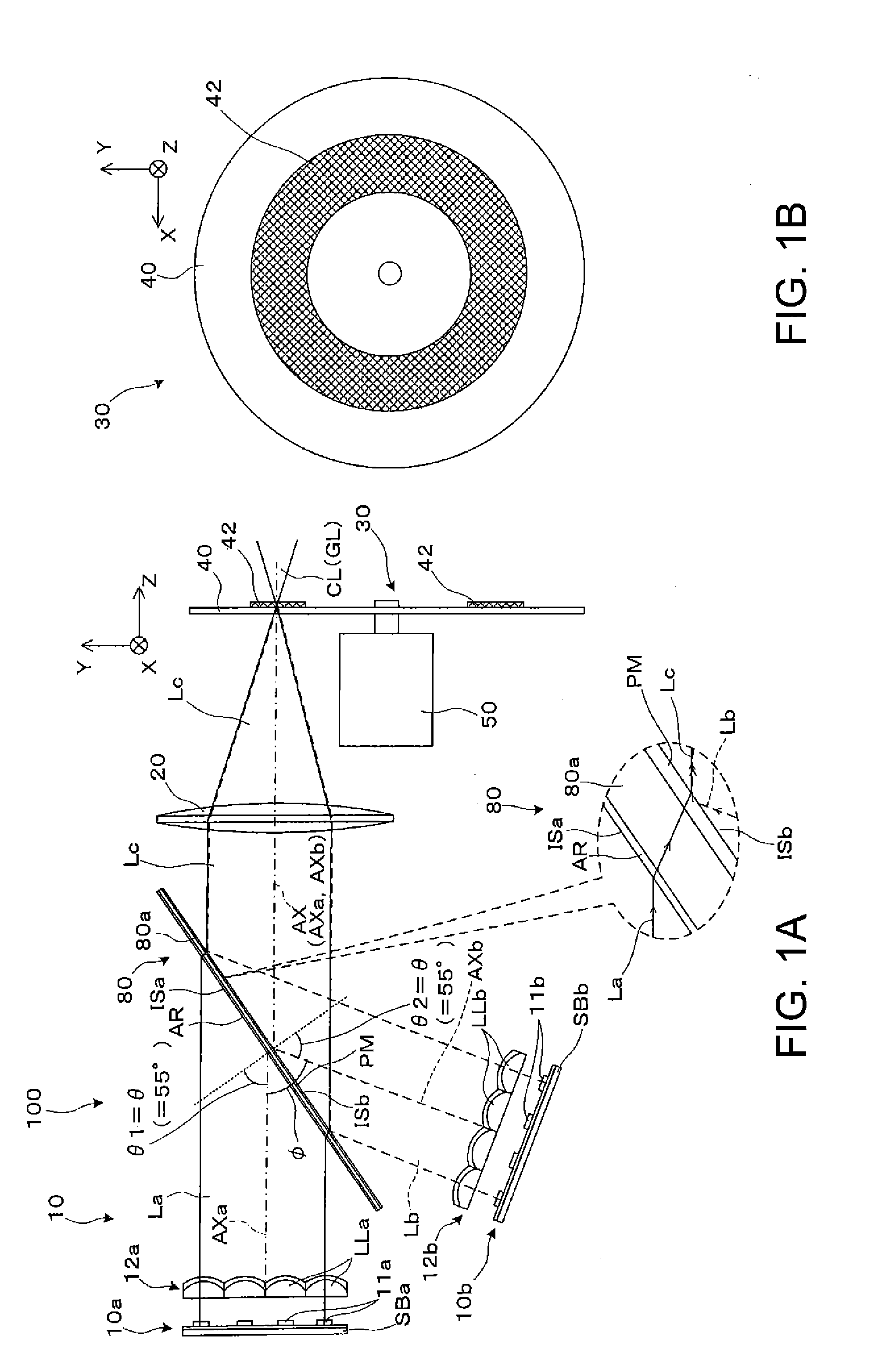
[0028]A light source apparatus 100 shown in FIG. 1A includes a light combiner 80, which combines laser light La, which is first light, emitted from a first light source unit 10a, and laser light Lb, which is second light, emitted from a second light source unit 10b to form light that will serve as light source light. The light source apparatus 100 includes an excitation light source 10, the light combiner 80, which combines light fluxes from the light source 10, a collector lens 20, which is a collector system, a rotating fluorescent plate 30, which is a rotating plate that rotatably holds a wavelength conversion element, and a motor 50. The light source 10 includes the first light source unit 10a, the second light source unit 10b, a collimation lens array 12a, which parallelizes light from the first light source unit 10a, and a collimation...

second embodiment

[0049]A light source apparatus according to a second embodiment will be described below. The light source apparatus according to the present embodiment is a variation of the light source apparatus 100 according to the first embodiment and differs therefrom only in terms of the structure downstream of the light combiner 80, and no overall description will therefore be made.

[0050]A light source apparatus 102 according to the present embodiment includes the light source 10, the light combiner 80, a Koehler illumination system 22, which makes the intensity distribution of the light from the light combiner 80 uniform, the collector lens 20, the rotating fluorescent plate 30, and the motor 50, as shown in FIG. 4. The light source 10 includes the first light source unit 10a and the second light source unit 10b. The Koehler illumination system 22, which includes an afocal system 22b, which adjusts the beam cross section of light, and a lens array integrator 22c, which divides light incident...

third embodiment

[0057]A projector including a light source apparatus will be described below as a third embodiment. FIG. 5 shows an example of a projector including the light source apparatus described above. FIG. 5 shows a projector 800 using the light source apparatus 102 shown in FIG. 4 by way of example, but the light source apparatus 102 can be replaced with the light source apparatus 100 shown in FIGS. 1A and 1B.

[0058]The projector 800 shown in FIG. 5 includes, as an apparatus that forms illumination light, an illuminator 110 including the light source apparatus 102. The illuminator 110 includes a pickup lens group 60 formed of a pickup lens 60a and a pickup lens 60b, a first lens array 120, a second lens array 130, a polarization conversion element 140, and a superimposing lens 150 as well as the light source apparatus 102 described above. The projector 800 further includes a color separation / light guiding system 200, a liquid crystal light modulator 400R, a liquid crystal light modulator 40...


PUM


Abstract

A light combiner having a polarization separation film and transmitting P-polarized light from a first light source unit whereas reflecting S-polarized light from a second light source unit forms combined light, and the angle of incidence of the light from the first light source unit and the angle of incidence of the light from the second light source unit with respect to the polarization separation film are each greater than 45°.

Description

BACKGROUND[0001]1. Technical Field[0002]The present invention relates to a light source apparatus having a plurality of light sources and a projector using the light source apparatus.[0003]2. Related Art[0004]As an illuminator useable, for example, with a projection-type video display apparatus, there is a known illuminator using a plurality of light sources and collecting light fluxes therefrom into a single light flux to efficiently form illumination light without any increase in size of the illuminator (JP-A-2011-158502). In JP-A-2011-158502, a pair of light sources are used and they output light fluxes polarized in different directions and in different degrees. A polarizer that transmits the linearly polarized light from one of the light sources and reflects the linearly polarized light from the other light source collects the light fluxes from the plurality of light sources.[0005]In JP-A-2011-158502, however, for example, depending on the wavelength band of each of the light fl...

Claims


Application Information

Patent Timeline
Patent Type & Authority Applications(United States)
IPC IPC(8): G03B21/20F21V9/14
CPCF21V9/14G03B21/2073G03B21/2013G03B21/2033G03B21/204G03B21/208
Inventor MATSUBARA, TAKAYUKI
Owner SEIKO EPSON CORP
Why Eureka
Try Eureka