Method and Apparatus for Controlling an Electric Motor and an Internal Combustion Engine
Active Publication Date: 2012-05-24
GASOLINEFREE
View PDF1 Cites 2 Cited by
- Summary
- Abstract
- Description
- Claims
- Application Information
AI Technical Summary
Benefits of technology
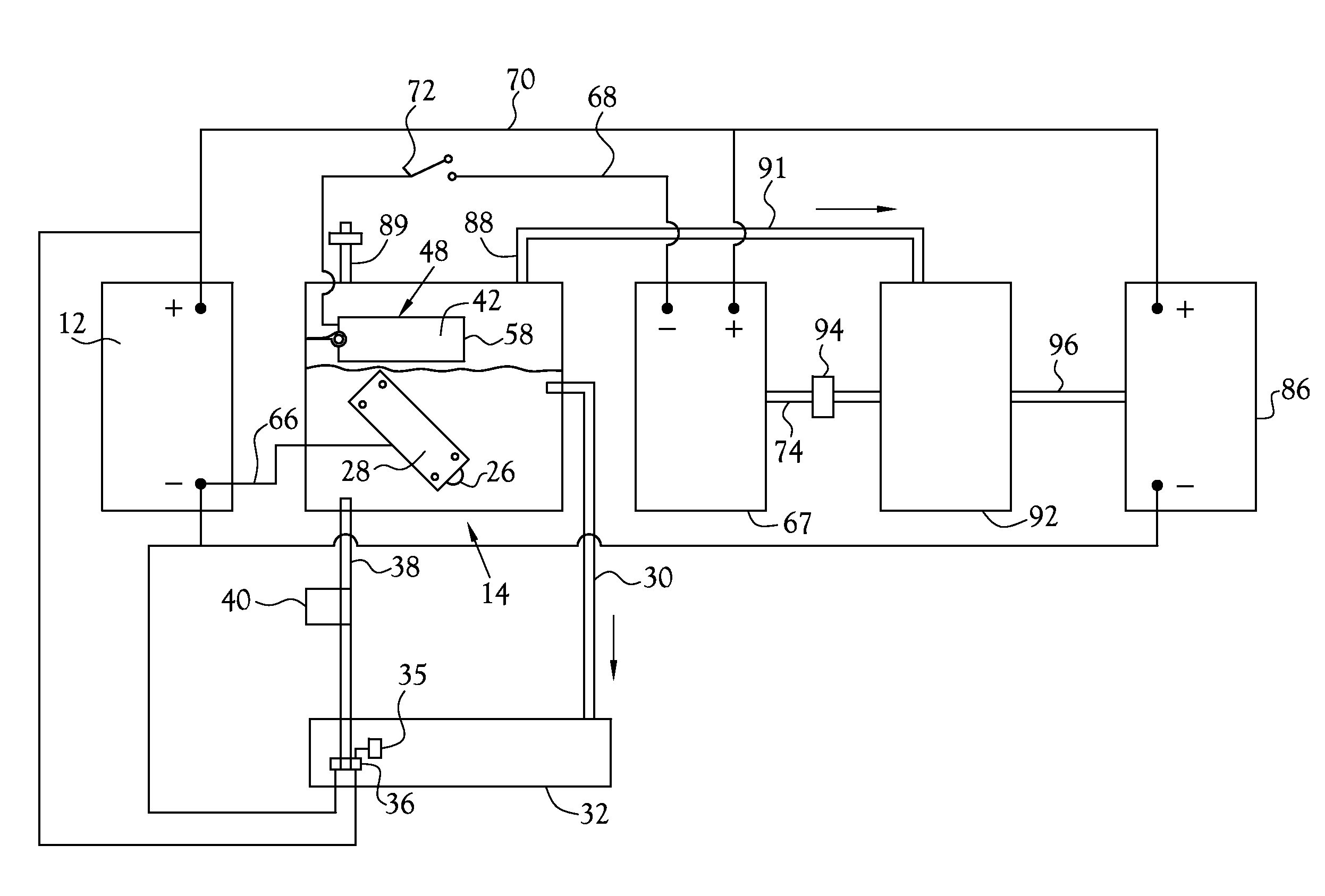
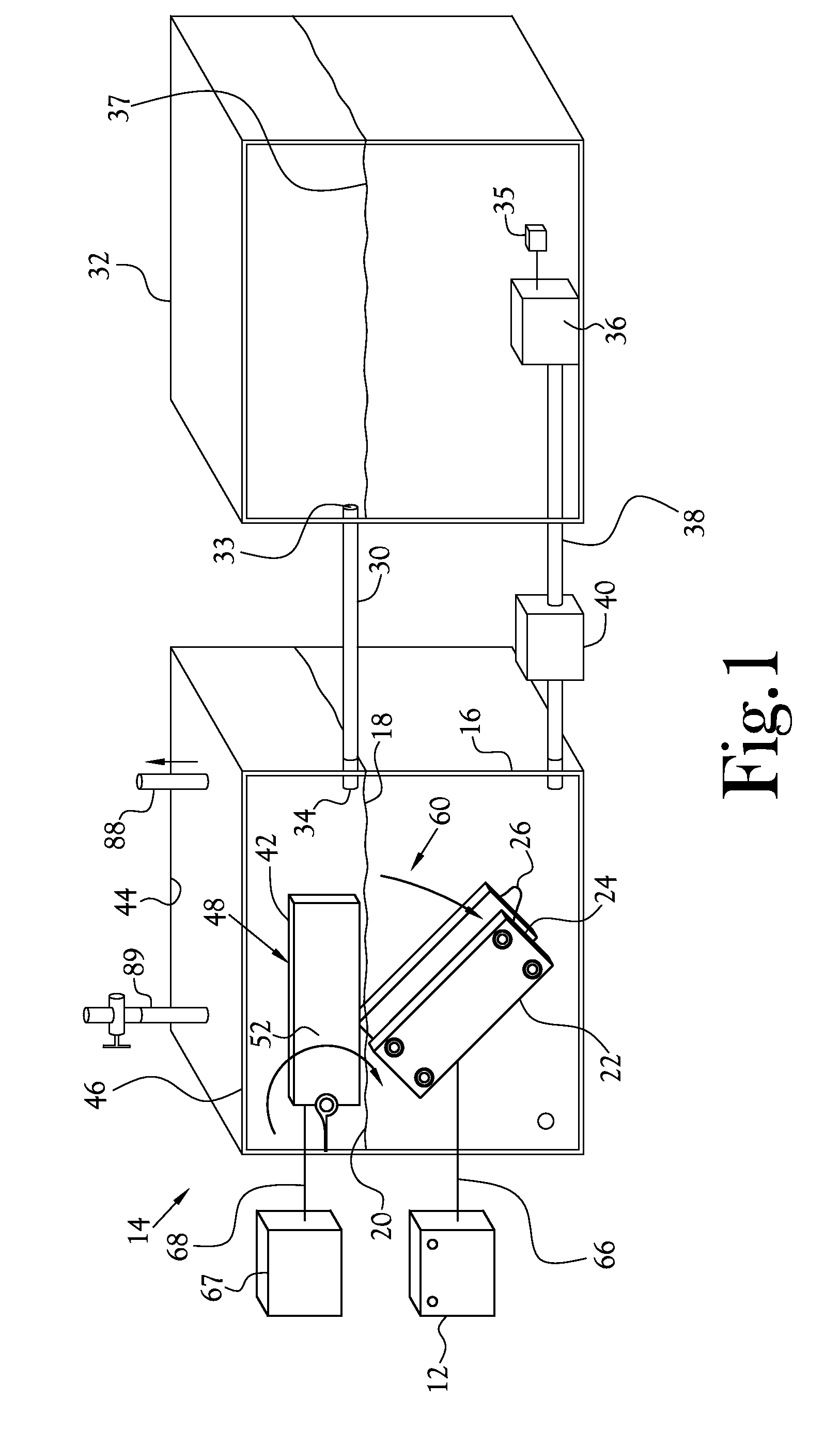
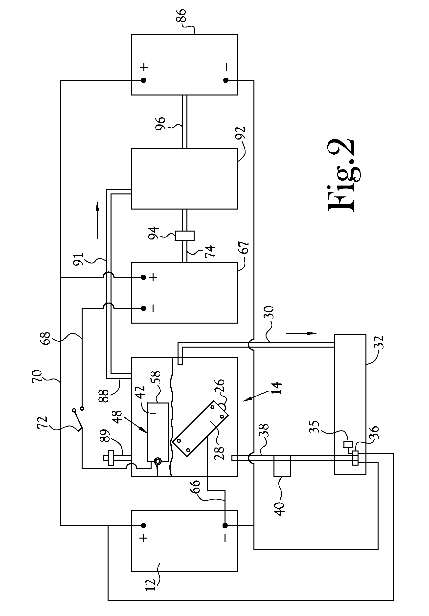
[0012]The electrolysis process of the present invention may be powered by a battery or battery pack in an electrical circuit which includes the motor. The electrodes of the electrolysis unit include first and second, preferably planar, electrically conductive plates, which are electrically connected to collectively define a first electrode. These parallel plates are mounted in registered, spaced-apart, substantially parallel planar relationship to one another within the electrolyte and are adjustable with respect to their spaced apart spatial relationship. There is further included a planar second plate electrode of substantially like size and geometry as the first and second plates of the first electrode. This second electrode is movable between a first position out of the electrolyte (hence out of register with the plates of the first electrode) and a second position within the electrolyte and partially or substantially fully interposed between the first and second plates, and substantially equidistant from and aligned (in register) with the first and second plates of the first electrode. According to one aspect of the present invention, the degree of regist
Problems solved by technology
Such prior art devices most commonly generate significant amounts of heat during operation of the motor.
Such devices are subject to damage by overheating and/or electrical spikes (both high and low) and/or overvoltage or undervoltage.
These controllers may exhibit lesser heat problem, but they are most sensitive to damage by electri
Method used
View moreImage
Smart ImageViewing Examples

Examples
 PUM
 Abstract
Method and apparatus for controlling an electric motor employing an electrolysis subassembly connected in an electrical circuit which includes the electric motor. While controlling the throughput of electrical current through the electrolysis subassembly, a fuel gas useful for fueling an internal combustion engine is simultaneously generated. The invention includes a novel electrolyte utilizing novel electrode structure and mode of operation.
Description
CROSS-REFERENCE TO RELATED APPLICATIONS[0001]This application is a continuation-in-part of prior U.S. patent application Ser. No. 12 / 203,621, filed Sep. 3, 2008, which is incorporated herein by reference.STATEMENT REGARDING FEDERALLY-SPONSORED RESEARCH OR DEVELOPMENT[0002]Not ApplicableBACKGROUND OF THE INVENTION[0003]1. Field of Invention[0004]This invention relates to methods and apparatus for controlling the operation of an electric motor or an internal combustion engine (ICE). As a beneficial byproduct, there is generated a volume of fuel gas suitable for a variety of uses.[0005]2. Description of the Related Art[0006]Electric motors commonly require means to control the operational speed of the motor(s). For example, in the prior art, control over the speed of rotation of the motor rotor, hence the rotational output of the motor shaft, has taken the form of variable resistors, rheostats, and like devices for adjusting the electrical input employed to drive the motor, such as the...
Claims
Login to View More Application Information
Patent Timeline
 IPC IPC(8): F02B43/00
CPCC25B9/12Y02T10/32F02B43/10C25B11/02C25B9/30Y02T10/30
Inventor HENRY, ZACHARY A.GAMMONS, RICKY L.
Owner GASOLINEFREE