Method For Controlling A Brushless Electric Motor

a brushless electric motor and sensorless technology, applied in the direction of motor/generator/converter stopper, electronic commutator control, dynamo-electric converter control, etc., can solve the problems of inability to effectively control the motor, the inability to integrate zero crossing identification, which is necessary for sensorless commutation, and the inability to achieve integrated zero crossing identification, etc., to achieve the effect of increasing the braking effect and dissipating mechanical energy

Active Publication Date: 2014-10-09
MINEBEAMITSUMI INC
View PDF21 Cites 16 Cited by
  • Summary
  • Abstract
  • Description
  • Claims
  • Application Information

AI Technical Summary

Benefits of technology

[0015]The second phase, the braking phase, lasts from zero crossing up to the end of the commutation interval. In this phase, at least two motor phases are actively short-circuited for a short time. The short-circuit causes an abrupt braking of the motor. When the short-circuit is then released, the short-circuit current stored in the inductance of the motor phases is fed back into the power supply. Mechanical energy is hence transformed via the short-circuit and current recovery and is thus dissipated. The switching time for the short-circuit is set such that the resulting short-circuit current in the motor phases is not too high. By repeating this process several times during a braking phase, sufficient mechanical energy can be dissipated. The braking effect can be further increased by short-circuiting all three motor phases. Alternatively, an appropriately configured PWM may be applied intermittently or continuously which runs the motor as a generator. These switch-on and switch-off times of the individual bridges are arranged such that the resulting voltage at the motor phases is lower than the BEMF voltage, which means that the motor current becomes negative and energy is fed back. During the above-mentioned switch-off time, at least two of the three lower switches of the bridge are closed, whereby the motor is momentarily short-circuited and thus an inductor of two of the three phase windings U,V,W is charged with current via the BEMF voltage. After the bridge has been switched over, during switch-on time, the current stored in the relevant phase windings is then made available via the now closed upper switch of the modulated branch of the bridge for driving the motor. Depending on the ratio of the switch-on time to the switch-off time, the resulting motor current will be larger or smaller. For example, whereas at a nominal rotational speed of 2000 rpm and a ratio of 70% switch-on time to 30% switch-off time, a positive motor current of 100 mA occurs, for the inverse ratio of 30% switch-on time to 70% switch-off time, at the same rotational speed, a negative motor current of −10 mA occurs, having the corresponding braking effect. This possibility of reversing the direction of the motor current is fundamental.

Problems solved by technology

However, this could also mean that the force of weight alone, without any current, drives the motor above the desired rotational speed.
On braking, several measured variables of the motor change their sign and can thus no longer be measured by unsophisticated electronics, for example, which is why the motor can no longer be effectively controlled.
The integrated zero crossing identification, which is necessary for sensorless commutation, may also be thereby impaired.
Due to the braking operation, negative phase currents occur, for example, that could entail undesirable disturbances and effects.
Additionally, any switching spikes that may occur have to be filtered, which makes the control circuit more complex and expensive.
The negative current cannot be measured by the available current measuring device.
In addition, overvoltages may possibly occur in the internal power supply that could cause damage.
Instead, it has to be dissipated which means additional, more complex circuitry has to be provided.
Regulation of the rotational speed in the braking operation is thus only made possible using additional measurement technology that can also process negative currents, which, however, is complex and expensive.
The short-circuit causes an abrupt braking of the motor.
Non-consumed energy is fed back into the power supply or, should this not be possible, causes an increase in the internal supply voltage.

Method used


Image

  • Method For Controlling A Brushless Electric Motor
  • Method For Controlling A Brushless Electric Motor
  • Method For Controlling A Brushless Electric Motor

Examples


Embodiment Construction

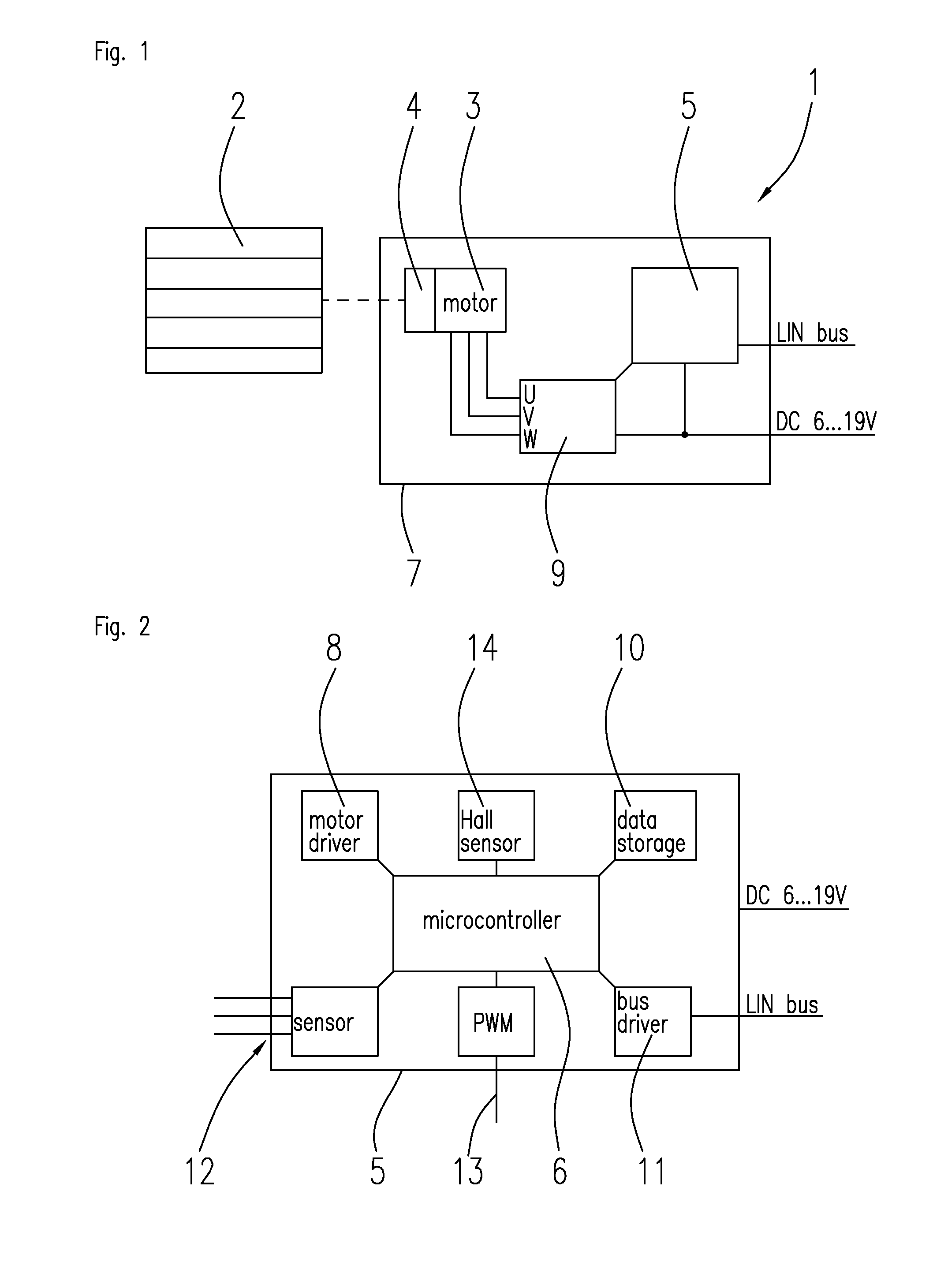
[0026]Examples of the invention are explained on the basis of an actuator 1 that is used to control air flaps 2 in a motor vehicle (FIG. 1). It is of course clear that the invention is in no way limited to this application and can be used in many other applications without any further changes.

[0027]The actuator 1 is a completely integrated solution in which a drive motor 3, a transmission 4 and the control electronics 5 together with a microcontroller 6 are disposed in a water-and dust-proof housing 7. Owing to its application in a motor vehicle, the actuator 1 is subject to a series of requirements that can only be realized by this integrated design.

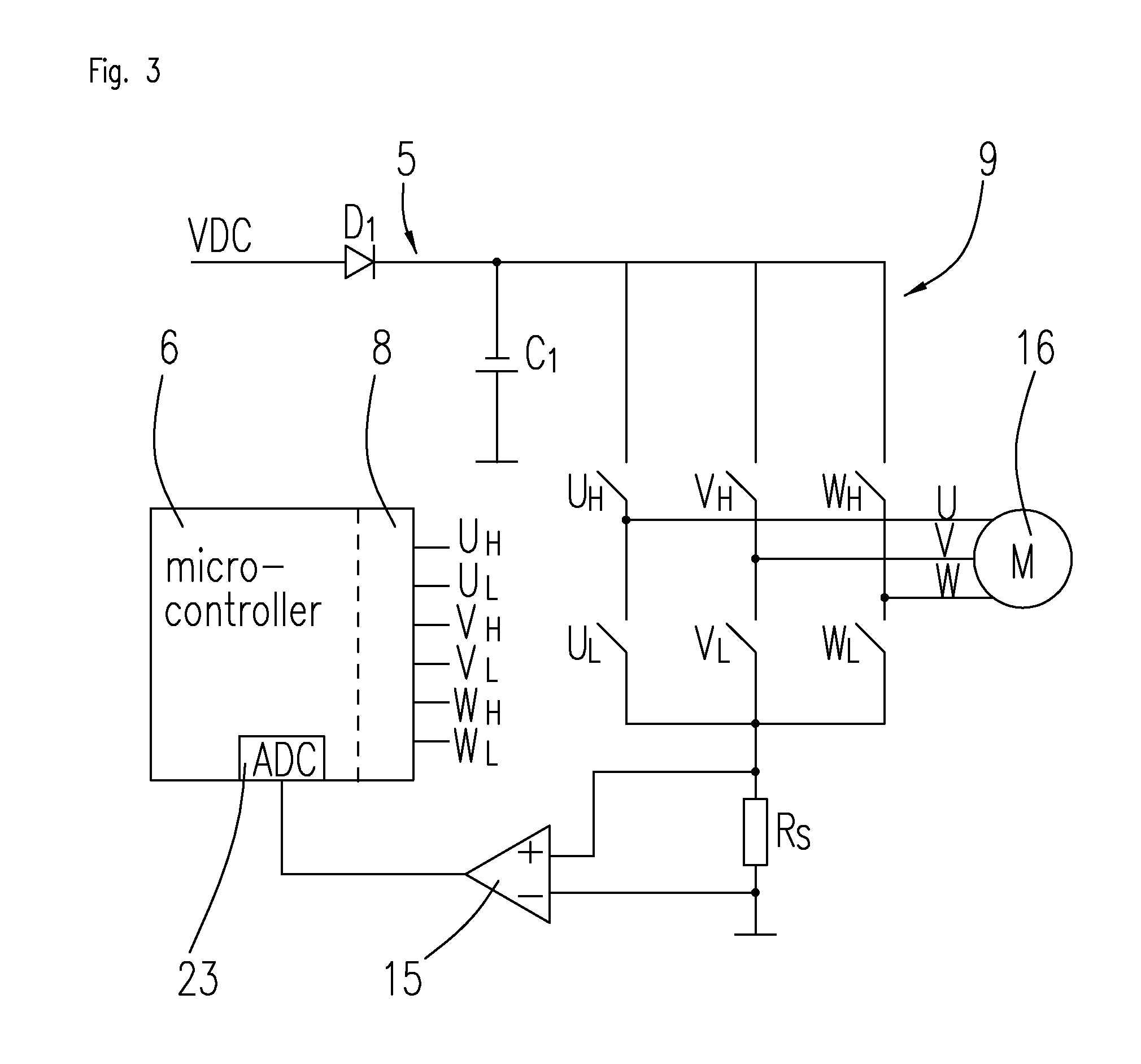
[0028]The drive motor 3 is a brushless DC motor that is controlled via a motor driver 8 having a switching bridge 9. The motor driver 8 forms a part of the microcontroller. The switching bridge 9 is controlled by the microcontroller 6.

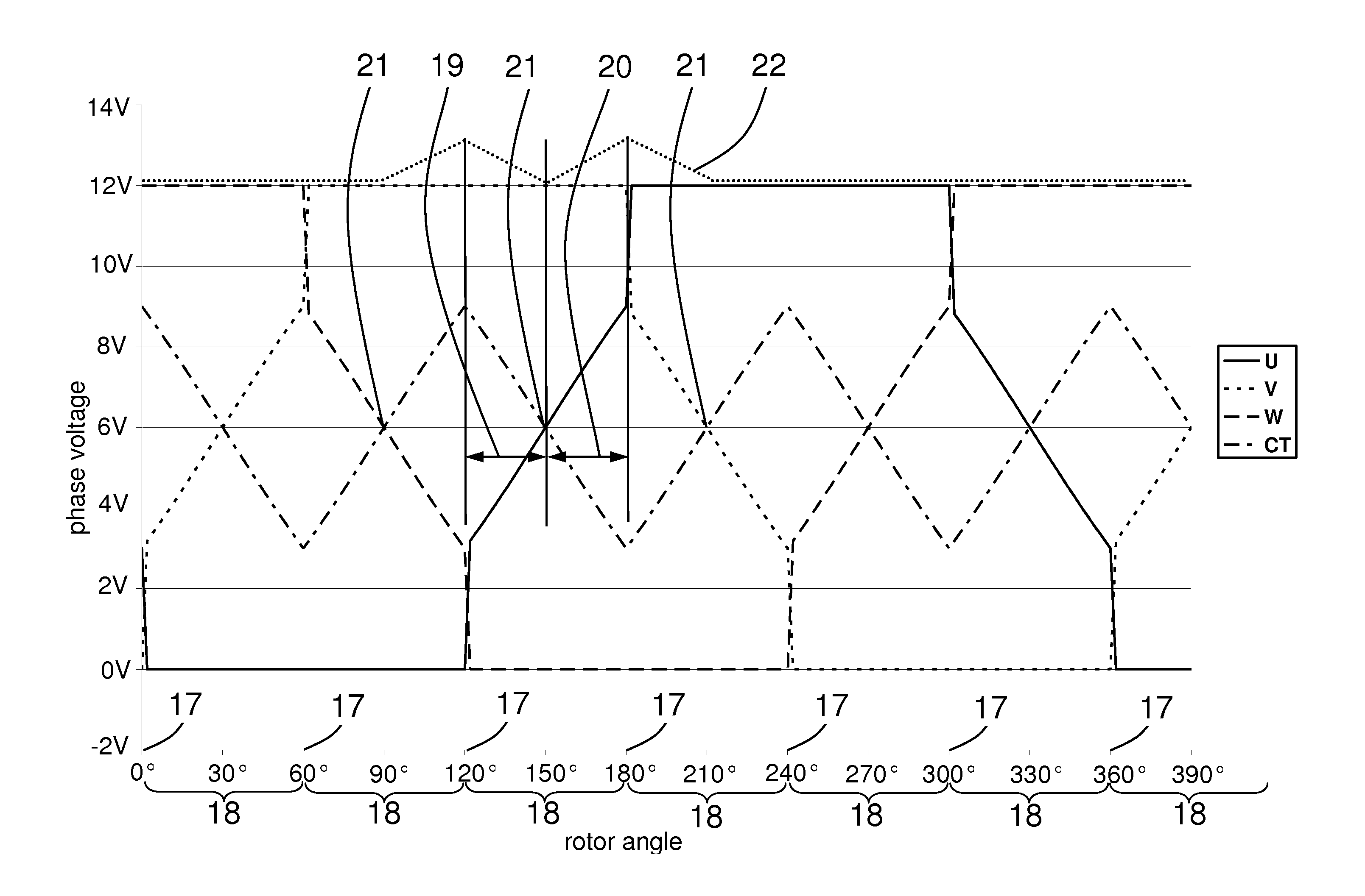
[0029]The motor has, for example, 6 or 12 magnetic poles and 9 stator slots. The harmonic frequencies i...


PUM


Abstract

The invention describes a method for controlling a sensorless, brushless DC motor that is controlled via a bridge circuit preferably using pulse width modulation (PWM) having precommutation. According to the invention, in the braking operation each commutation interval is divided into two phases. A drive phase, lasting from the start of the commutation interval up to zero crossing in which the motor is controlled with the normal PWM, and a braking phase, lasting from zero crossing up to the next commutation time in which at least two motor phases are short-circuited and/or in which the PWM is operated with recovered energy. The efficiency of the control circuit is as low as possible so as to ensure that the braking energy is consumed in the control circuit.

Description

FIELD OF THE INVENTION[0001]The invention describes a method for operating a sensorless, brushless electric motor, used particularly for braking the motor.BACKGROUND OF THE INVENTION[0002]The invention is based on a sensorless, brushless electric motor that is used in a motor vehicle as an actuator for flaps, such as air flaps or spoilers. For this kind of actuator, it is desirable if the electric motor is operated at a constant rotational speed. For this purpose, the electric motor preferably has a control having pulse width modulation (PWM).[0003]Depending on the position of the air flaps, it so happens that the weight that acts on the air flaps reinforces the movement of the motor. In order to achieve a desired rotational speed, a lower motor current is then required.[0004]However, this could also mean that the force of weight alone, without any current, drives the motor above the desired rotational speed. In this case, the motor would have to be actively braked so as to attain t...

Claims


Application Information

Patent Timeline
Patent Type & Authority Applications(United States)
IPC IPC(8): H02P3/12
CPCH02P3/12H02P6/14H02P6/15
Inventor WINKER, MARTINMOOSMANN, KLAUS
Owner MINEBEAMITSUMI INC
Why Eureka
Try Eureka