
Spacer plate and support structure

a technology of support structure and spacer plate, which is applied in the direction of rod connection, dismountable cabinets, furniture parts, etc., can solve the problems of not fitting and/or looking proper, and the display of the profile in the horizontal direction is mainly horizontal

Active Publication Date: 2012-05-24
BARCO NV
View PDF14 Cites 12 Cited by
  • Summary
  • Abstract
  • Description
  • Claims
  • Application Information

AI Technical Summary

Benefits of technology

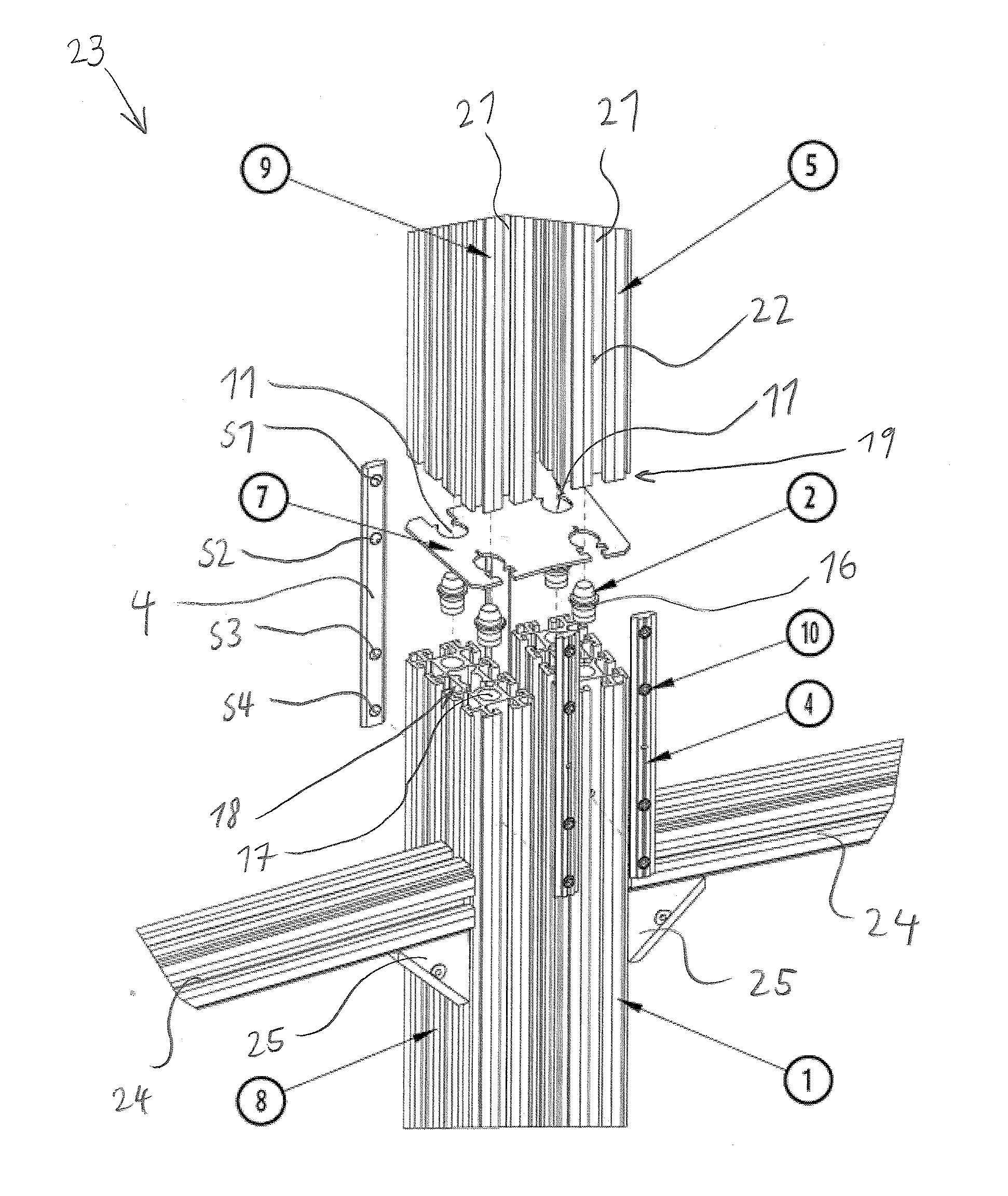
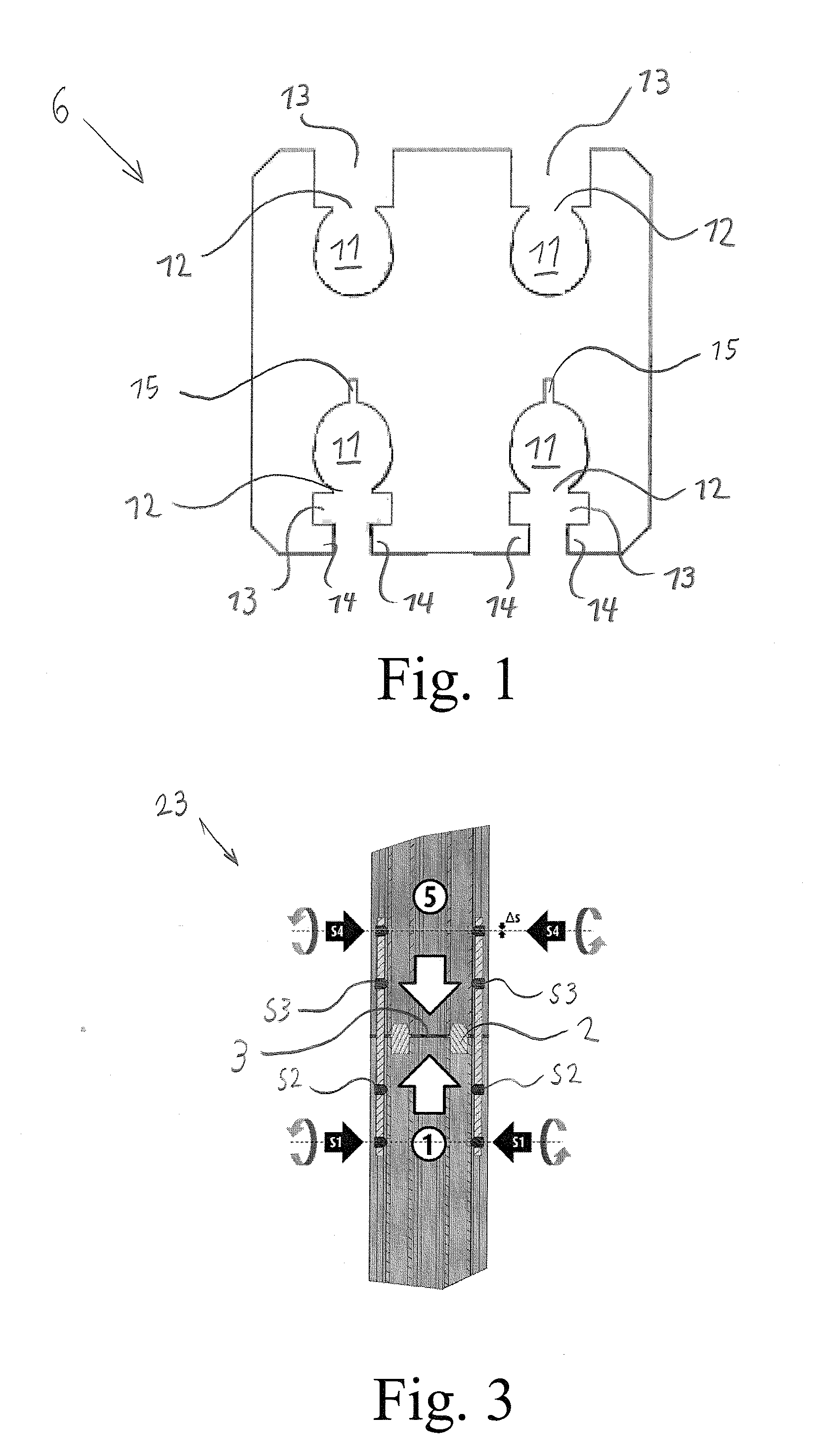
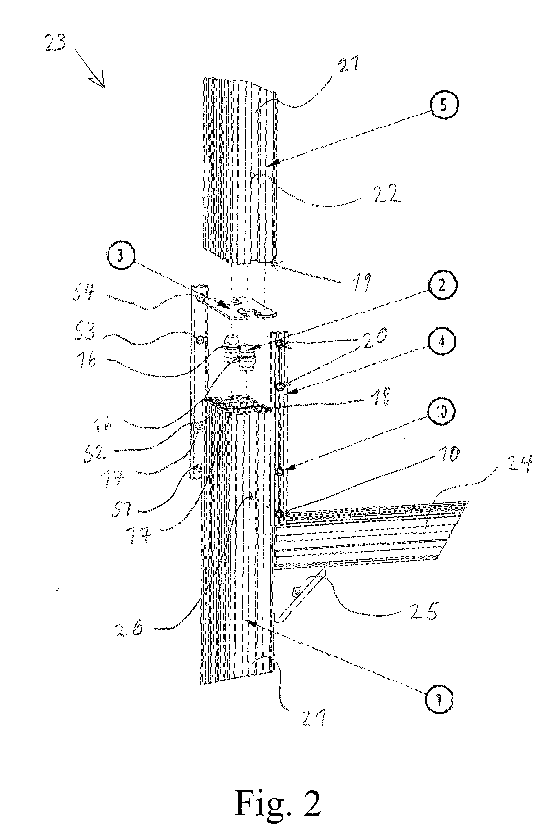
The present invention provides a device and method for connecting support profiles of a display support structure with high accuracy without hindering the assembly process. The device includes a spacer plate with an alignment opening for receiving an alignment stud and a connector opening for connecting the profiles. The alignment opening and connector opening can be designed to align with corresponding features in the profiles. The device allows for easy alignment of the support profiles and ensures stability and stability of the support structure. The use of the spacer plate and connector bar eliminates free play between the profiles and reduces tolerances. The connector bar can be widened to clamp the alignment stud within the alignment opening. The invention provides an improved and more accurate method for connecting support profiles.

Problems solved by technology

If not, displays connected to profiles in mainly horizontal direction would not fit and / or would not look proper.

Method used


Image

  • Spacer plate and support structure
  • Spacer plate and support structure
  • Spacer plate and support structure

Examples


Embodiment Construction

[0026]The present invention will be described with respect to particular embodiments and with reference to certain drawings but the invention is not limited thereto but only by the claims. The drawings described are only schematic and are non-limiting. In the drawings, the size of some of the elements may be exaggerated and not drawn on scale for illustrative purposes. The dimensions and the relative dimensions do not correspond to actual reductions to practice of the invention.

[0027]Furthermore, the terms first, second, third and the like in the description and in the claims, are used for distinguishing between similar elements and not necessarily for describing a sequence, either temporally, spatially, in ranking or in any other manner. It is to be understood that the terms so used are interchangeable under appropriate circumstances and that the embodiments of the invention described herein are capable of operation in other sequences than described or illustrated herein.

[0028]More...


PUM


Abstract

A spacer plate (3, 6, 7) for interconnecting support profiles (1, 5, 8, 9) of a display support structure (23) is described, including at least one alignment opening (11) for receiving an alignment stud (2) for aligning a first profile (1, 8) with respect to a second profile (5, 9) via the spacer plate (6), and at least one connector opening (13) for receiving a connector bar (4) for connecting the first profile (1, 8) to the second profile (5, 9) via the spacer plate (6), wherein the connector opening (13) is connected to the alignment opening (11) such that the relative position of the alignment stud (2) inside the alignment opening (11) is adjustable by the position of the connector bar (4) inside the connector opening (13). This allows to easily put the alignment stud (2) into the alignment opening (11) of the spacer plate (3, 6, 7) or vice versa and to eliminate all free play between the alignment stud (11) and the spacer plate (3, 6, 7) at the same time. The assembly of the support structure (23) is not hampered. At the same time a self centering of the alignment stud (2) with respect to the spacer plate (3, 6, 7) can be forced leading to an increased accuracy, when the profiles (1, 5, 8, 9) are connected to each other.

Description

FIELD OF THE INVENTION[0001]The present invention relates to a spacer plate for interconnecting support profiles of a display support structure or the like as well as a display support structure for providing a fence and / or supporting a display or the like, e.g. including a spacer plate and a method of making a display support structure for providing a fence and / or supporting a display or the like, e.g. including a spacer plate.BACKGROUND OF THE INVENTION[0002]It is known to interconnect a plurality of profiles for providing a support structure like a fence or a display wall. The plurality of profiles can be connected to each other in an H-like manner easily. When the support structure is used as part of a display wall, it is important that particularly the profiles in mainly vertical direction are highly accurate aligned. If not, displays connected to profiles in mainly horizontal direction would not fit and / or would not look proper.SUMMARY OF THE INVENTION[0003]It is an object of ...

Claims


Application Information

Patent Timeline
Patent Type & Authority Applications(United States)
IPC IPC(8): H05K7/18F16B7/00
CPCA47B47/027A47B96/1466A47F5/10Y10T403/559F16B7/0406F16B12/40F16B5/0008Y10T403/55Y10T403/557Y10T403/57Y10T403/5753F16B5/00F16B5/025
Inventor DECROOS, MARCDEWAELE, TOM
Owner BARCO NV
Learn More