Apparatus for Dispensing Plastic Bags

a dispenser and plastic bag technology, applied in metal-working apparatus, domestic applications, thin material processing, etc., can solve the problems of long string of bags hanging from the roll, difficult for consumers to separate bags from the rolls, and inconvenient opening of the dispenser, so as to reduce the footprint of bags and dispensers, easy to separate from the rolls, and easy to open

Inactive Publication Date: 2012-05-24
DURATECH PLASTICS CORP
View PDF13 Cites 40 Cited by
  • Summary
  • Abstract
  • Description
  • Claims
  • Application Information

AI Technical Summary

Benefits of technology

[0005]Embodiments of the present invention provide an apparatus for dispensing plastic bags on a roll. Embodiments of the present invention reduce footprint of bags and dispenser and make each bag easier to separate from roll. Further, embodiments of the present invention prevent the roll of bags from spinning out of control thereby leaving a string of bags hanging from the dispenser. Embodiments of the present invention may also provide a dispenser in which the bags are folded in such a way so each bag is easier to open.

Problems solved by technology

Many retailers are concerned that dispensers for the rolls of plastic bags require too much shelf space and / or floor space.
Although there are perforations between the bags on the roll, on many occasions it can be difficult for consumers to separate a bag from the roll.
In some cases, the roll may roll too much causing a long string of bags to hang from the roll when a consumer attempts to separate a bag from the roll.
Many retailers feel that such a long string of bags hanging from a roll is an eyesore and a potential safety hazard.
Another problem a consumer can encounter is that after a bag is separated from a roll the next bag on the roll can lie flat on the surface of the roll making it difficult for a consumer to find and / or grab the next bag.

Method used


Image

  • Apparatus for Dispensing Plastic Bags
  • Apparatus for Dispensing Plastic Bags
  • Apparatus for Dispensing Plastic Bags

Examples


Embodiment Construction

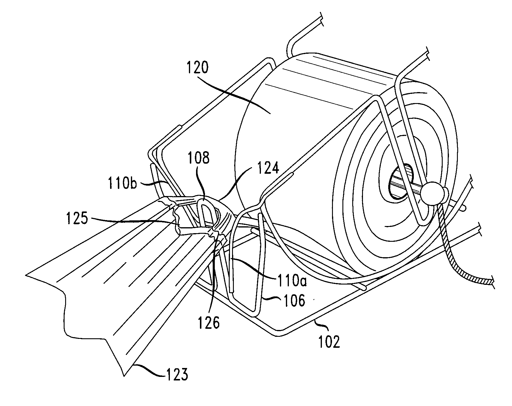
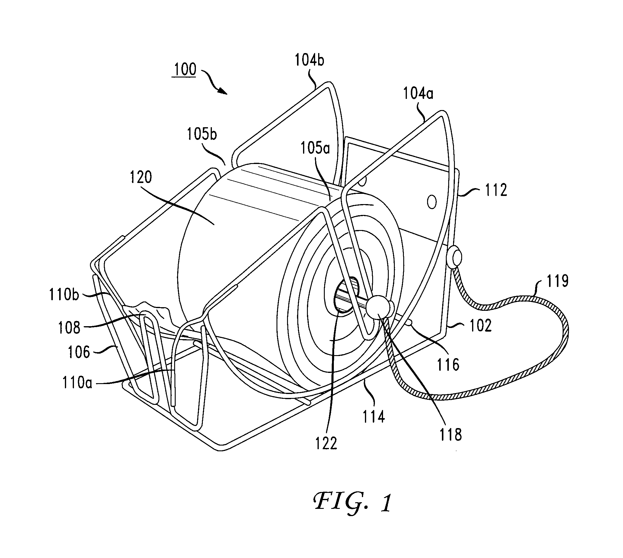
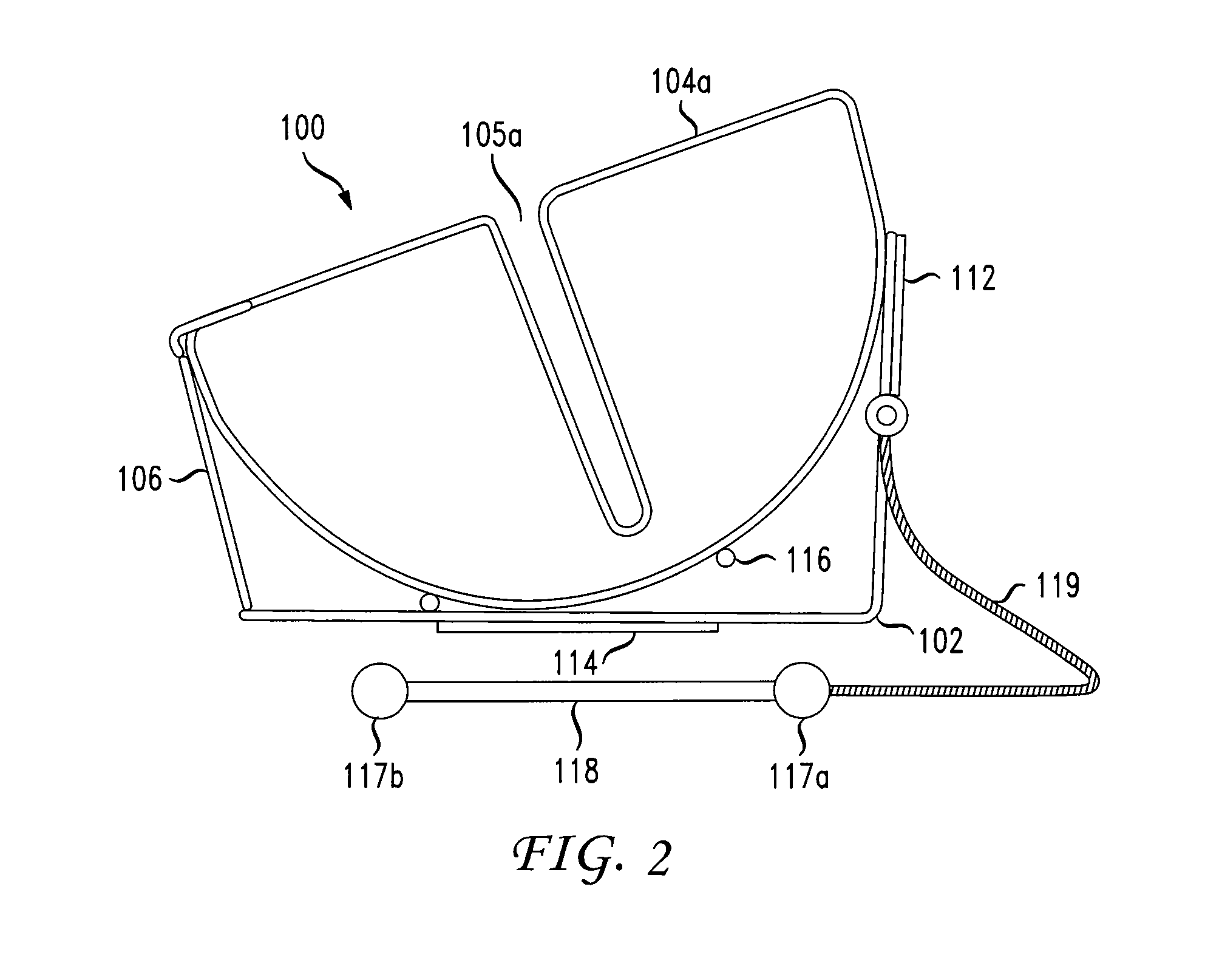
[0019]FIG. 1 is a perspective view of an apparatus for dispensing bags on a roll according to an embodiment of the present invention. As illustrated in FIG. 1, the apparatus includes a dispensing rack 100 capable of housing a roll of plastic bags 120. FIG. 2 is a side view showing the dispenser rack 100. FIG. 3 is a side view showing the roll of bags 120 and the dispenser rack 100. FIG. 4 is a side view showing the roll of bags seated within the dispenser rack.

[0020]As illustrated in FIGS. 1 and 2, the dispensing rack 100 includes a base 102 that is substantially “L” shaped, two semi-circular sides 104a and 104b attached to the base 102, and a front portion 106 attached to the base 102 and the sides 104a and 104b. The front portion 106 of the dispensing rack 100 includes a tongue 108, which may be integrally formed with the front portion 106 of the dispensing rack 100. The dispensing rack 100 also includes wedges 110a and 110b. The wedges 110a and 110b may be connected to the sides ...


PUM


Abstract

An apparatus for dispensing plastic bags is disclosed. The apparatus includes a dispensing rack having a base, opposing sides, and a front portion. The opposing sides include tracks that accommodate a spindle capable of being inserted through a core of a roll of plastic bags and into the tracks such that the roll of plastic bags is seated in the dispenser rack and rotatable with respect to the spindle. The front portion of the dispensing rack is formed with a tongue which engages with a slit between bags on a roll and causes a bag to separate along a perforation. The front portion of the dispensing rack may also be formed with wedges which angle downward from the sides of the dispensing rack toward a lower portion of the tongue. When a bag is detached, the wedges catch the next bag and hold the next bag in place.

Description

[0001]This application claims the benefit of U.S. Provisional Application No. 61 / 416,084, filed Nov. 22, 2010, the disclosure of which is herein incorporated by reference.BACKGROUND OF THE INVENTION[0002]The present disclosure relates generally to a dispenser for dispensing plastic bags on a roll.[0003]In various types of stores, such as supermarkets, food markets, hardware stores, etc., plastic bags on a roll are typically available for bulk purchase of various items, such as produce, bakery products, and hardware parts. The rolls of plastic bags are typically the same width as the bags and many rolls are typically provided in a store for the convenience of consumers. Many retailers are concerned that dispensers for the rolls of plastic bags require too much shelf space and / or floor space. Many retailers are also concerned about the aesthetic appearance of plastic bag dispensers and the functionality provided to consumers.[0004]Rolls of plastic bags are typically mounted horizontal...

Claims


Application Information

Patent Timeline
Patent Type & Authority Applications(United States)
IPC IPC(8): B65H35/10
CPCA47F13/085B65H2701/191B65H35/10A47F2009/044Y10T225/393
Inventor TSUI, JONATHAN J.
Owner DURATECH PLASTICS CORP
Why Eureka
Try Eureka