Exploitation Of Sea Floor Rig Structures To Enhance Measurement While Drilling Telemetry Data

a technology of telemetry and sea floor, applied in the direction of sealing/packing, instruments, borehole/well accessories, etc., can solve the problems of affecting the quality of drilling rigs, requiring drilling assembly to be removed, and requiring drilling rigs to be rented by the day at a substantial cos

Active Publication Date: 2012-05-24
HALLIBURTON ENERGY SERVICES INC
View PDF24 Cites 96 Cited by
  • Summary
  • Abstract
  • Description
  • Claims
  • Application Information

AI Technical Summary

Benefits of technology

[0016]Thus, embodiments described herein comprise a combination of features and advantages intended to address various shortcomings associated with certain prior devices, systems, and methods. The various characteristics described above, as well as other features, will be readily apparent to those skilled in the art upon reading the following detailed description, and by referring to the accompanying drawings.

Problems solved by technology

One problem with obtaining downhole measurements via wireline is that the drilling assembly must be removed or “tripped” from the drilled borehole before the wireline can be lowered downhole to obtain the desired borehole information.
This can be both time-consuming and extremely costly, especially in situations where a substantial portion of the well has been drilled.
Typically, drilling rigs are rented by the day at a substantial cost.
Consequently, the cost of drilling a well is directly proportional to the time required to complete the drilling process.
Removing thousands of feet of tubing to insert a wireline logging tool is often an expensive proposition.
However, offshore MWD operations pose numerous difficulties to conventional mud pulse, acoustic, and EM telemetry systems and methods and often impose undesirable limitations on data transfer rates and / or depth ranges.

Method used


Image

  • Exploitation Of Sea Floor Rig Structures To Enhance Measurement While Drilling Telemetry Data
  • Exploitation Of Sea Floor Rig Structures To Enhance Measurement While Drilling Telemetry Data
  • Exploitation Of Sea Floor Rig Structures To Enhance Measurement While Drilling Telemetry Data

Examples


Embodiment Construction

[0037]The following discussion is directed to various embodiments of the invention. Although one or more of these embodiments may be preferred, the embodiments disclosed should not be interpreted, or otherwise used, as limiting the scope of the disclosure, including the claims. In addition, one skilled in the art will understand that the following description has broad application, and the discussion of any embodiment is meant only to be exemplary of that embodiment, and not intended to intimate that the scope of the disclosure, including the claims, is limited to that embodiment.

[0038]Certain terms are used throughout the following description and claims to refer to particular features or components. As one skilled in the art will appreciate, different persons may refer to the same feature or component by different names. This document does not intend to distinguish between components or features that differ in name but not function. The drawing figures are not necessarily to scale...


PUM


Abstract

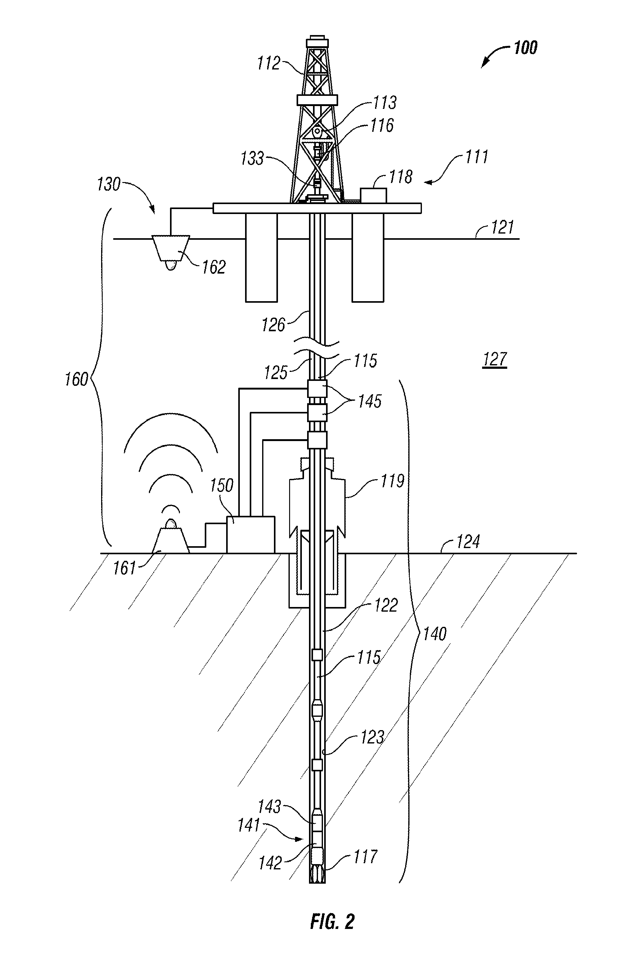
A method for communicating data in an offshore data communication system comprises measuring L/MWD data with a sensor disposed in a bottomhole assembly positioned in a subsea borehole. The bottomhole assembly is disposed along a drillstring extending through the subsea borehole. In addition, the method comprises communicating the L/MWD data from the bottomhole assembly to the seafloor with a telemetry signal. Further, the method comprises receiving the telemetry signal with at least one telemetry transducer positioned proximal the sea floor. Still further, the method comprises processing the telemetry signal at the seafloor to produce a processed signal. Moreover, the method comprises transmitting the processed signal from the sea floor to the sea surface.

Description

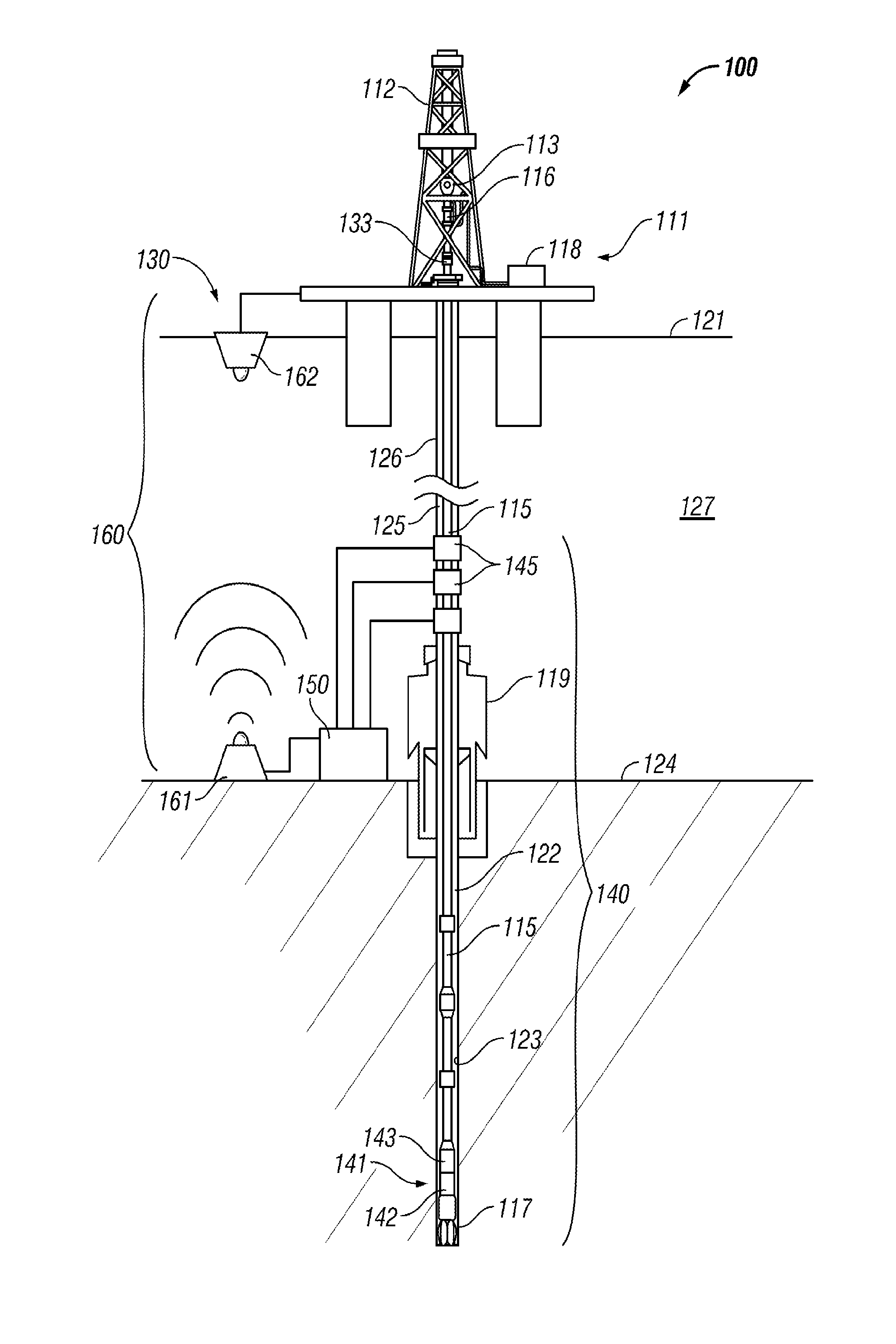
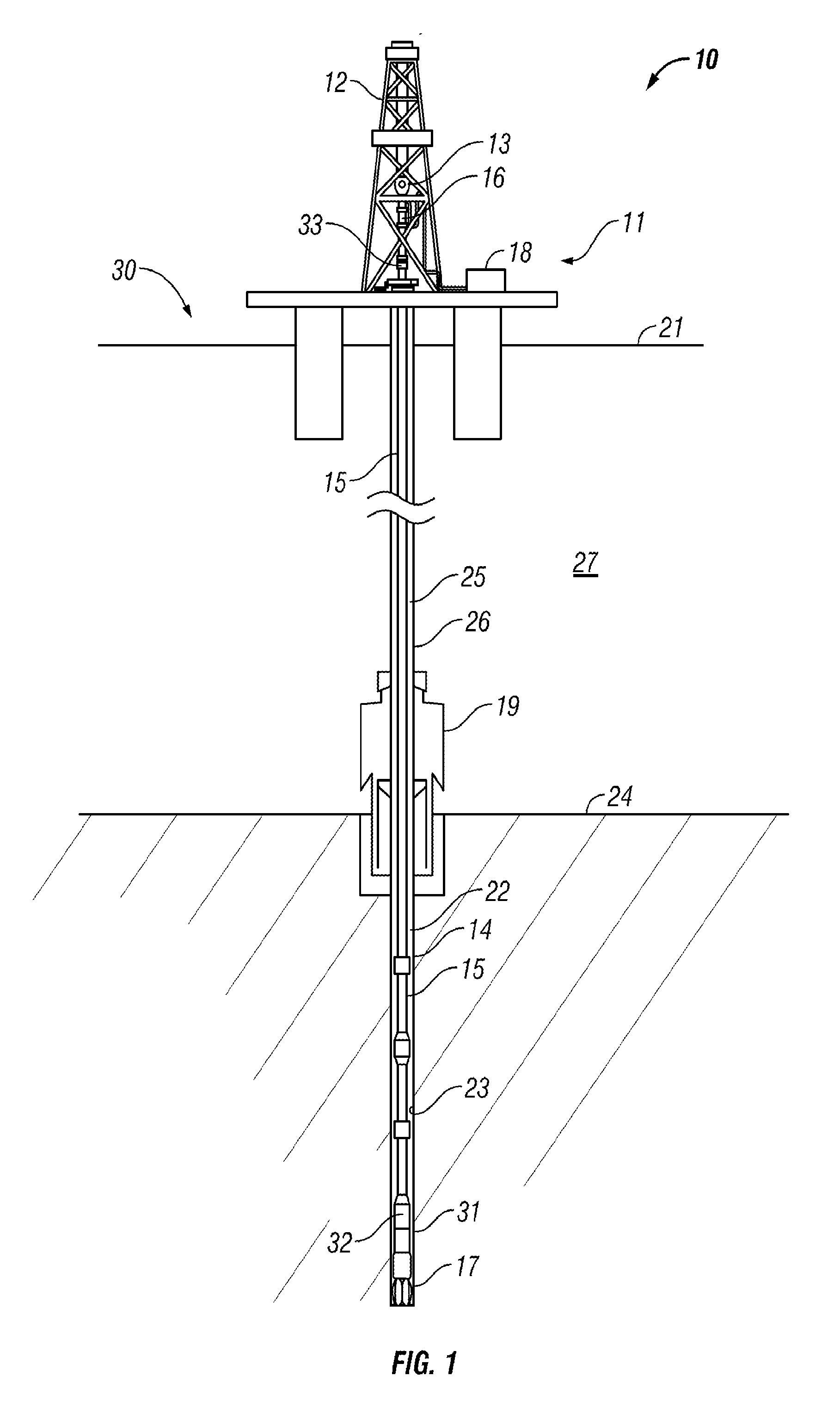
STATEMENT REGARDING FEDERALLY SPONSORED RESEARCH OR DEVELOPMENT[0001]Not applicable.BACKGROUND[0002]1. Field of the Invention[0003]The invention relates generally to subsea data communications systems and methods. More particularly, the invention relates to a subsea data telemetry systems and methods that leverage sea floor rig structures to enhance the quality of the telemetry data.[0004]2. Background of the Technology[0005]Modern petroleum drilling and production operations demand a great quantity of data and information relating to downhole conditions and drilling and production parameters. Such information typically includes characteristics of the earth formations traversed by the wellbore, as well as data relating to the size and configuration of the borehole itself. The collection of information relating to downhole conditions, commonly referred to as “logging”, can be performed by a variety of methods.[0006]In conventional oil well wireline logging, a probe or “sonde” that ho...

Claims


Application Information

Patent Timeline
Patent Type & Authority Applications(United States)
IPC IPC(8): H04B13/02
CPCE21B33/0355G01V11/002E21B34/10
Inventor RODNEY, PAUL F.DOWNING, ANDREW J.SPROSS, RONALD L.
Owner HALLIBURTON ENERGY SERVICES INC
Why Eureka
Try Eureka