Print Data Processing Method, Print Data Processing Device, And Print Data Processing System

a technology of data processing and data processing device, which is applied in the direction of digital output to print units, instruments, visual presentations, etc., can solve the problems of bleed-through and transparency, the problem of printing information on the front may be particularly easily affected, and the print on the back may bleed through to the front. , to achieve the effect of high print density and reliably preventing the effect of causing a drop in readability

Active Publication Date: 2012-05-24
SEIKO EPSON CORP
View PDF9 Cites 19 Cited by
  • Summary
  • Abstract
  • Description
  • Claims
  • Application Information

AI Technical Summary

Benefits of technology

[0024]The invention adjusts first-surface print data and second-surface print data for printing both sides of a recording medium so that barcode data or other first print data that is printed on a first surface is not printed at a position overlapping second print data such as graphic data that is printed on a second surface on the opposite side. A graphic with a high print density printed on one side bleeding through to or being visible from the other side can therefore be reliably prevented from causing a drop in the readability or a drop in the scanning accuracy of a barcode or other content printed on the other side.

Problems solved by technology

When receipts are thus printed on both sides, however, the content printed on the reverse side may be visible from the front, or the printing on the back may bleed through to the front.
If printing on one side thus overlaps printing on the other side, the readability of information printed on the front may be undesirably reduced.
When a thermal head is used for printing both sides of the paper, the heat-sensitive coating on the surface of one side may change color when the other side is printed, a problem also referred to herein as “bleed-through.” When a graphic that is dark or has a high print density is printed on the back, the content printed on the back may be visible through the paper when reading the printing on the front.
These problems of bleed-through and transparency occur particularly easily when using thin paper.
Therefore, if the recording medium is printed on both sides using the first print data and second print data after the data is adjusted, problems caused by image bleed-through and images printed on one side being visible on the other side will not occur because the printing positions of the first print data and second print data do not overlap.

Method used


Image

  • Print Data Processing Method, Print Data Processing Device, And Print Data Processing System
  • Print Data Processing Method, Print Data Processing Device, And Print Data Processing System
  • Print Data Processing Method, Print Data Processing Device, And Print Data Processing System

Examples


embodiment 1

Generating Print Data on the Host Device

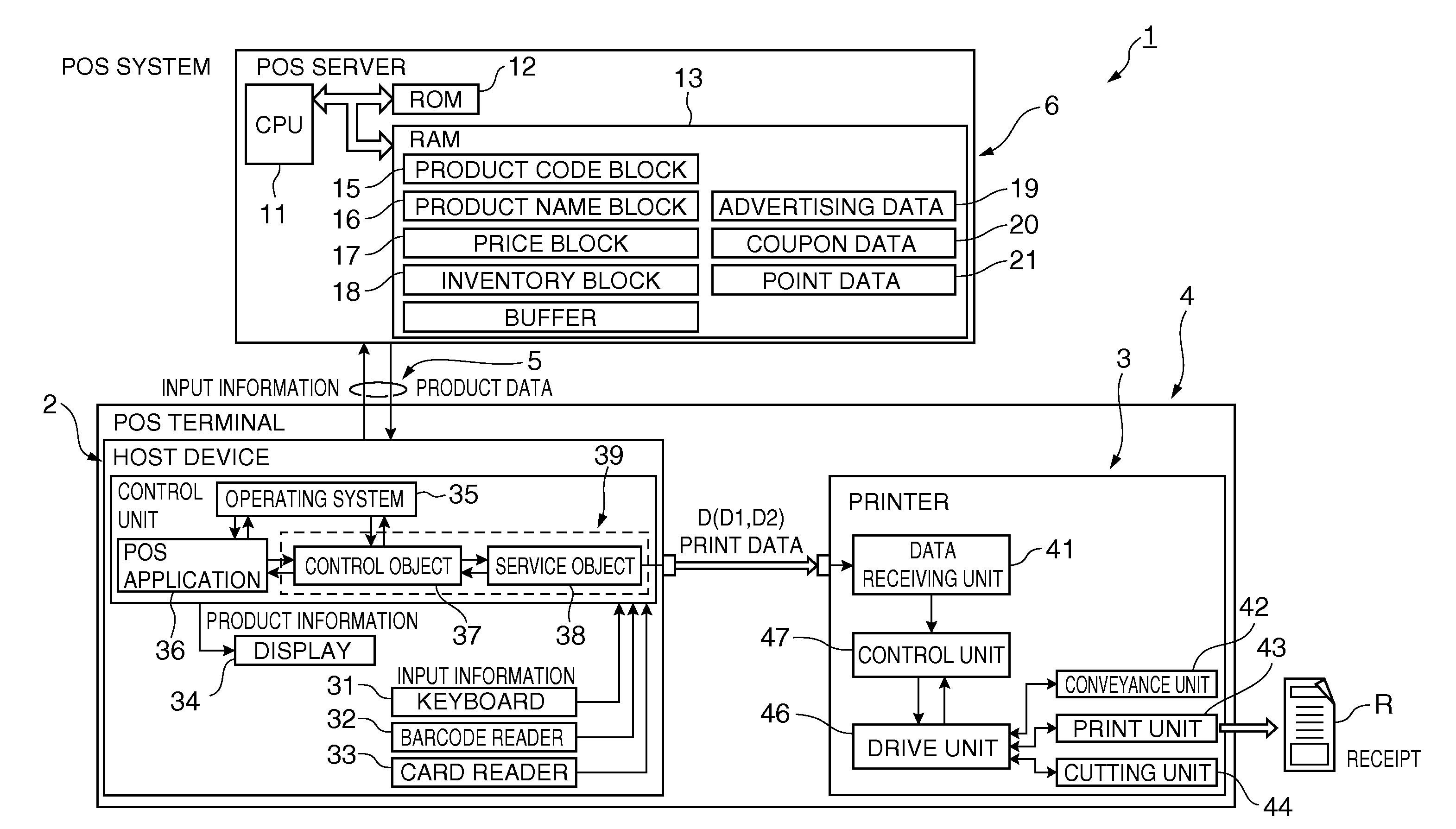
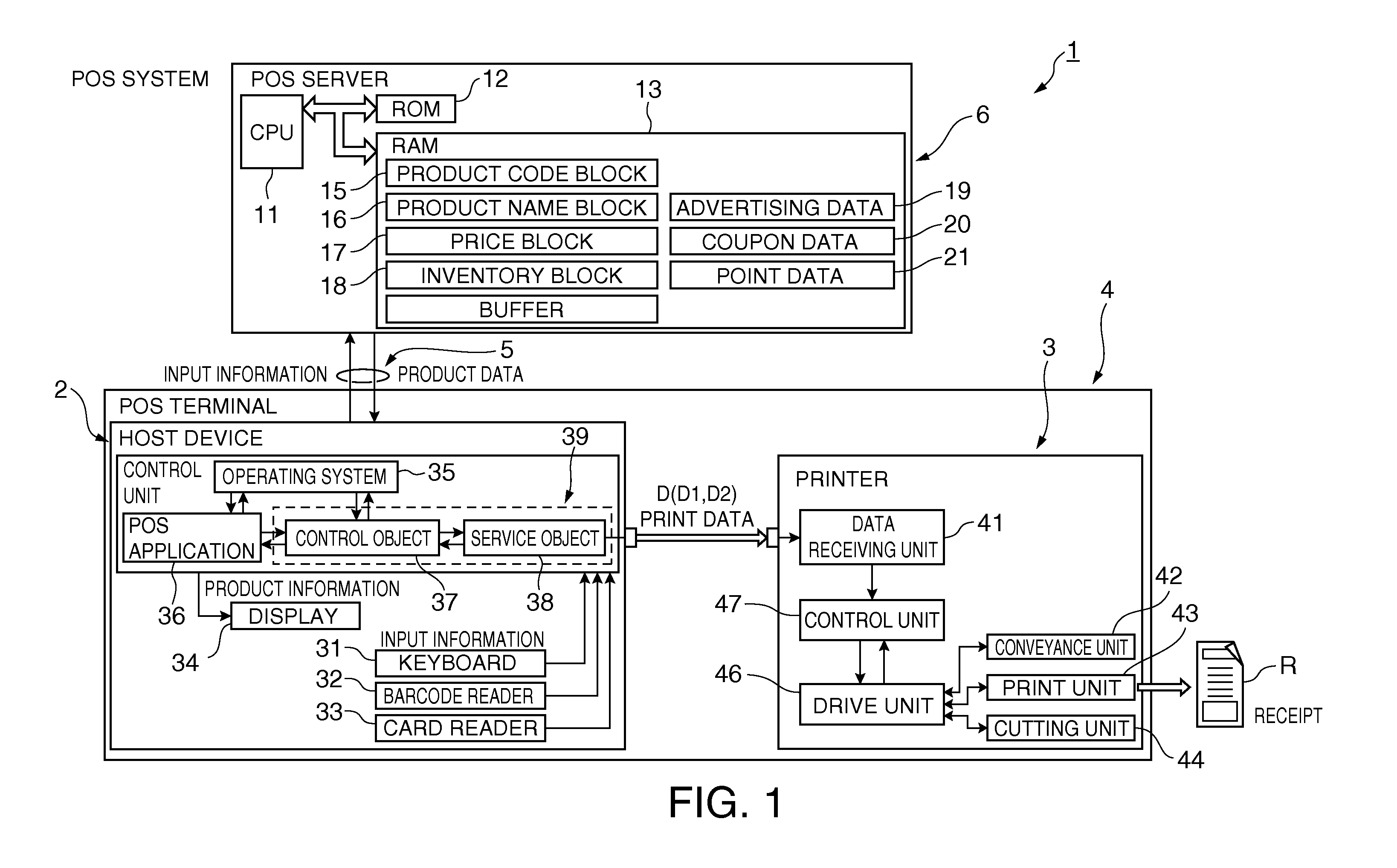
[0058]FIG. 3 is a flow chart showing the steps executed by the POS application 36 of the host device 2 to generate front print data D1 and back print data D2. FIG. 4 shows an example of a method of adjusting the printing position on the receipt R, FRONT indicating the placement of the front print data D1, BACK indicating the placement of the back print data D2, and BACK AFTER ADJUSTMENT indicating the placement of the back print data D2 after printing position adjustment.

[0059]Referring to these figures, when transaction data is received from the POS server 6 side, the host device 2 generates print data based on settings stored in the printer driver 39. If duplex printing is specified, front print data D1 and back print data D2 are generated as the print data D.

[0060]First, in step ST1 in FIG. 3, data in the transaction information is allocated according to a predefined front format, and based thereon the front print data D1 is generated in st...

example 1

[0069]In the example shown in FIG. 5, when plural graphics G1 to G4 are included in the back print data of the receipt R, the printing positions are adjusted by inserting white spaces S1, S2, S3 of a constant width between the graphics as shown under BACK in FIG. 5, for example, to generate the back print data D2. When the printing position of code data B in the front print data overlaps the printing position of graphic data G4 on the back side, the front print data D1 is generated by inserting white space S11 to the printing position of code data B in the front print data as shown in FRONT in FIG. 5 so that the printing position of code data B is adjusted to a position opposite white space S4 adjacent to graphic data G4.

example 2

[0070]When printing a receipt, the format of the receipt front generally includes a fixed-length print area A1 for printing graphic data G such as a store logo at the leading end of the receipt, a fixed-length print area A4 for code data B such as a transaction ID printed at the trailing end of the receipt, and print areas A2, A3 therebetween that vary in length according to the amount of transaction data as shown in FRONT in FIG. 6. These variable-length areas include variable-length area A2 where a store notice, for example, composed of text data T is printed, and a variable-length area A3 where transaction data composed of text data T is printed.

[0071]In this case, as shown in BACK in FIG. 6, the back print data area is also divided into print areas a1 to a4 corresponding to the front print areas A1 to A4, print area a4 corresponding to the front print area where code data B is printed is set as a no-print zone for graphic data G, and the printing positions are adjusted so that g...


PUM


Abstract

A print data processing method can generate print data for duplex printing so that the scanning accuracy of a barcode printed on one side of a receipt is not reduced by a logo or other graphic that is printed on the other side of the receipt. Whether or not a linear barcode or other code data B is contained in the front print data D1 that is printed on the front of the receipt is determined, and whether graphic data G is contained in the back print data D2 that is printed on the other side of the receipt is determined. If graphic data G is contained, the back print data D2 is adjusted so that the graphic data G is not printed to a position overlapping the code data B on the opposite side of the receipt.

Description

[0001]Priority is claimed under 35 U.S.C. §119 from Japanese patent application nos. JP 2010-259839 filed on Nov. 22, 2010 and JP 2010-259840 filed on Nov. 22, 2010, which are hereby incorporated by reference in their entirety.BACKGROUND[0002]1. Technical Field[0003]The present invention relates to a print data processing method, a print data processing device, and a print data processing system for appropriately printing on both sides of a receipt or other recording medium in a POS system, for example.[0004]2. Related Art[0005]POS systems used in retail stores that issue receipts printed on both sides by a receipt printer connected to the POS terminal are known from the literature. The store name, transaction details, and a barcode containing an ID code for identifying a particular transaction, for example, may be printed on the front of the receipt while a coupon or advertising, for example, may be printed on the back.[0006]Japanese Unexamined Patent Appl. Pub. JP-A-2009-123028 te...

Claims


Application Information

Patent Timeline
Patent Type & Authority Applications(United States)
IPC IPC(8): G06K15/02
CPCG06K15/1868G07G5/00
Inventor KOBAYASHI, NAOKI
Owner SEIKO EPSON CORP
Why Eureka
Try Eureka