Multi-coordinate orthodontic implant positioning device

a positioning device and orthodontic implant technology, applied in the field of orthodontic implant positioning devices, can solve the problems of inconvenient accuracy for dentists, undesired injures to patient's tooth roots, etc., and achieve the effect of reducing the rate of error, ensuring the required positioning accuracy, and more accurate positioning

Inactive Publication Date: 2012-05-24
YAO YIN CHAO
View PDF3 Cites 9 Cited by
  • Summary
  • Abstract
  • Description
  • Claims
  • Application Information

AI Technical Summary

Benefits of technology

[0012]In the present invention, the main coordinate system and the sub-coordinate system are two different and independent coordinate systems for positioning an implant point. The main coordinate system enables primary and quick positioning while the sub-coordinate system independent of the main coordinate system enables more accurate positioning. The present invention maintains the required accuracy in positioning while reduce the rate of error in determining the optimal implant point, and therefore effectively upgrades the efficiency in performing an orthodontic implant surgery.

Problems solved by technology

However, due to physical or anatomical differences among patients, or due to improper implant position, there is possibility the implanted orthodontic implant undesirably injures the patient's tooth roots.
While there are counting marks 93 provided on the measuring scales at regular intervals, it is still very inconvenient for the dentist to accurately determine the implant position for the orthodontic implant by counting the lines and rows of the tiny measuring scales.

Method used


Image

  • Multi-coordinate orthodontic implant positioning device
  • Multi-coordinate orthodontic implant positioning device
  • Multi-coordinate orthodontic implant positioning device

Examples


Embodiment Construction

[0022]The present invention will now be described with some preferred embodiments thereof and with reference to the accompanying drawings.

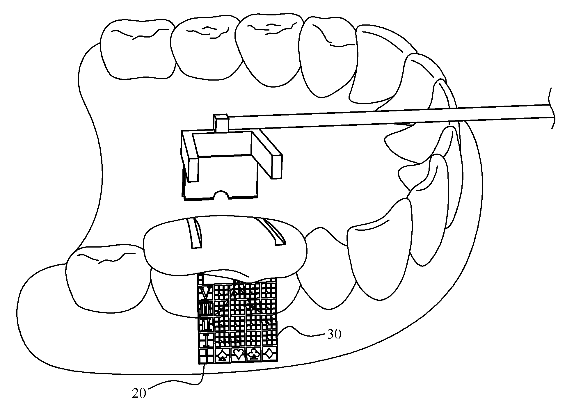
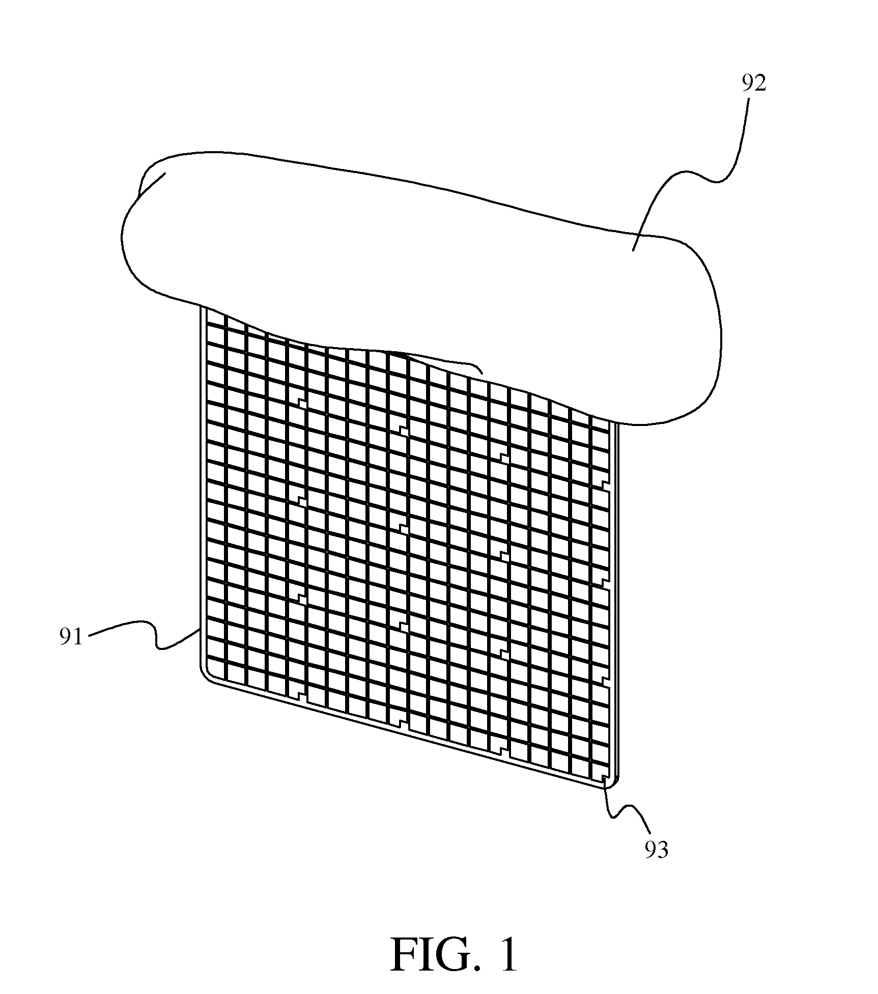
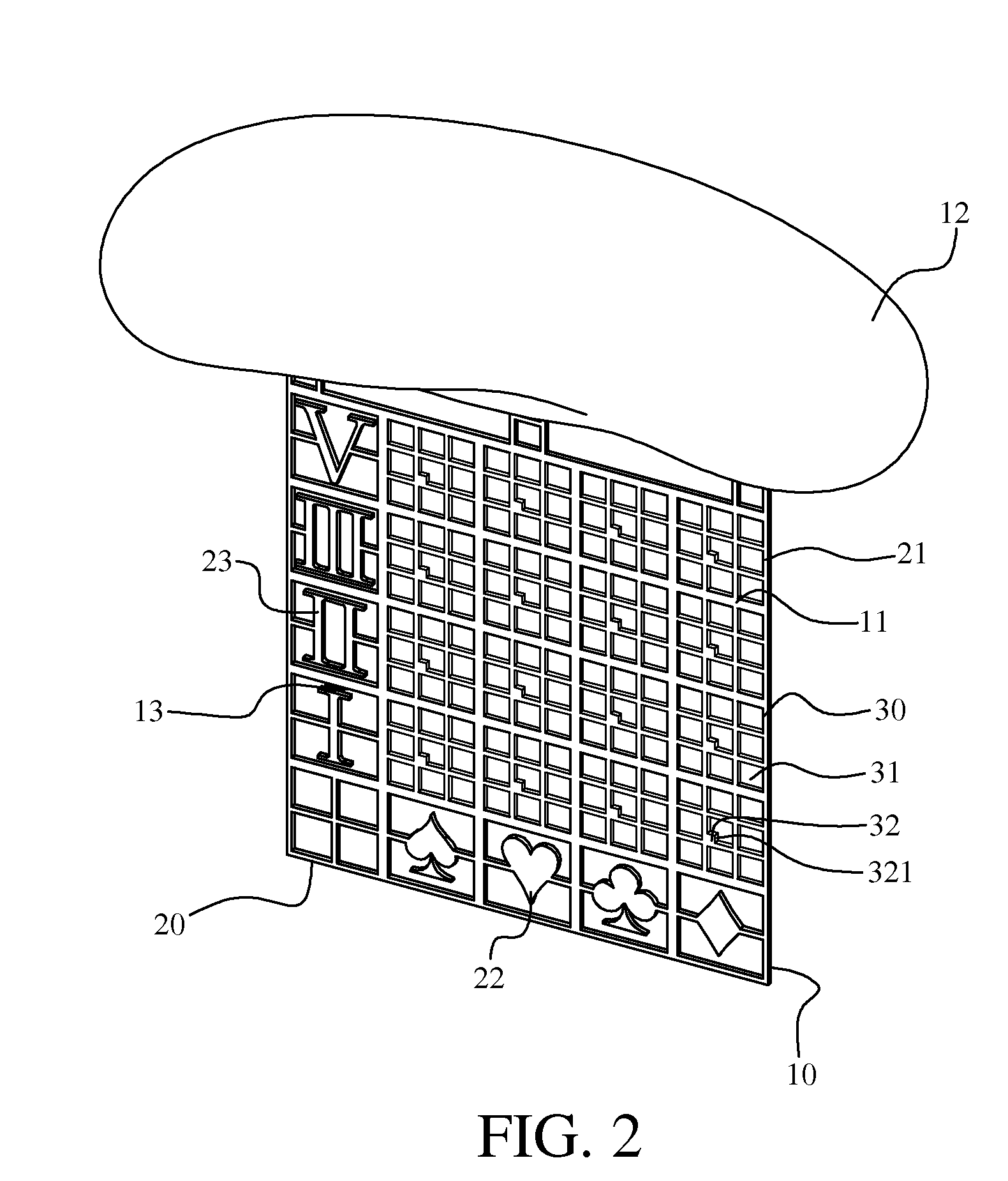
[0023]Please refer to FIGS. 2 and 3, in which a multi-coordinate orthodontic implant positioning device according to a first preferred embodiment of the present invention is shown. The multi-coordinate orthodontic implant positioning device includes a measuring reference member 10 that has, on the one hand, a predetermined thickness to possess sufficient strength for serving as a temporary support in the process of implanting an orthodontic implant and is, on the other hand, slim and light enough for disposing between a patient's two teeth at a cheek side or a tongue side thereof. On the measuring reference member 10, there is provided a plurality of measuring scales 11 formed of a radiopaque material. And, a fixing member 12 is connected to an edge of the measuring reference member 10 for fixedly attaching to the patient's teeth.

[0024]In the illu...


PUM


Abstract

A multi-coordinate orthodontic implant positioning device includes a measuring reference member having a predetermined thickness and being provided thereon with measuring scales formed of a radiopaque material. The measuring reference member is connected at an edge to a fixing member for fixedly attaching to the patient's teeth. The measuring scales define a coordinate-type positioning structure, which includes at least a main coordinate system and a sub-coordinate system. The main coordinate system divides the positioning structure into a plurality of coordinate blocks, each of which has a main coordinate code readable from the main coordinate system; and the sub-coordinate system is provided in some specified ones of the coordinate blocks. Since the main coordinate system and the sub-coordinate system are two different and independent coordinate systems, the use of them enables primary and more accurate positioning of an implant point to effectively upgrade the efficiency in the orthodontic implant surgery.

Description

FIELD OF THE INVENTION[0001]The present invention relates to an auxiliary positioning device used in orthodontics, and more particularly to a multi-coordinate orthodontic implant positioning device that provides an accurate measuring reference to enable quick determination in primary diagnosis to ensure accurate positioning of an optimal implant point.BACKGROUND OF THE INVENTION[0002]In recent years, implant orthodontics has been quickly and widely employed by orthodontic field for using in clinical orthodontic treatment. By implant orthodontics, it means the implanting of a mini-implant into a patient's alveolar bone to serve as a force application point and provide a stable source of pull for moving a patient's teeth, so as to achieve the best bite occlusion relationship and improved facial aesthetics as well as enhanced effect of orthodontic treatment. When the orthodontic treatment is completed, the mini-implant is removed from the patient's oral cavity. Thus, the mini-implant t...

Claims


Application Information

Patent Timeline
Patent Type & Authority Applications(United States)
IPC IPC(8): A61C7/00
CPCA61C1/084A61C8/0096A61C8/0089
Inventor YAO, YIN-CHAO
Owner YAO YIN CHAO
Why Eureka
Try Eureka