Centrifuge

a centrifuge and centrifugal force technology, applied in centrifugal force sediment separation, centrifugal force centrifuges, separation processes, etc., can solve the problems of limiting the utility of facilities with funds and space available, requiring considerable operator skills to complete procedures, and expensive capital equipmen

Active Publication Date: 2012-05-24
DSM IP ASSETS BV
View PDF0 Cites 23 Cited by
  • Summary
  • Abstract
  • Description
  • Claims
  • Application Information

AI Technical Summary

Benefits of technology

[0009]In accordance with the invention, a single use, sterile, self-contained, compact, easy to use centrifugal separation unit provides for quick, reliable platelet concentration from whole blood. The resultant PRP / PC can be immediately used for application to the patient. The unit is suitable for office, operating room, emergency use, or military field hospital use.
[0016]In another embodiment, the BSC, or at least a portion thereof, can be made of a clear material so that the progress of the red blood cell removal can be observed through a clear window in the outer case. This can allow for precise timing for closing the first port to end the exiting of the red blood cells.
[0017]Another embodiment accomplishes the concentration through precise timing of the valve opening / closing sequence and the starting and stopping of the motor.
[0018]In another embodiment, the system may feature a reusable drive component with a motor that is arranged to be coupled to a disposable centrifuge component, wherein the blood products are centrifuged, separated, and contained entirely within the disposable unit, such that the drive component is not exposed to blood product and may be reused without fear of contamination.
[0020]In another embodiment, the rotation chamber is arranged to minimize the disruption to the interfaces between the separated blood products, while the red blood cells and plasma components are evacuated from the rotating chamber.

Problems solved by technology

A major drawback to these methods is the need for an expensive piece of capital equipment which limits the utility to facilities that have the funds and space available.
These methods also require considerable operator skills to complete the procedures necessary to obtain the PRP / PC.

Method used


Image

  • Centrifuge
  • Centrifuge
  • Centrifuge

Examples


Embodiment Construction

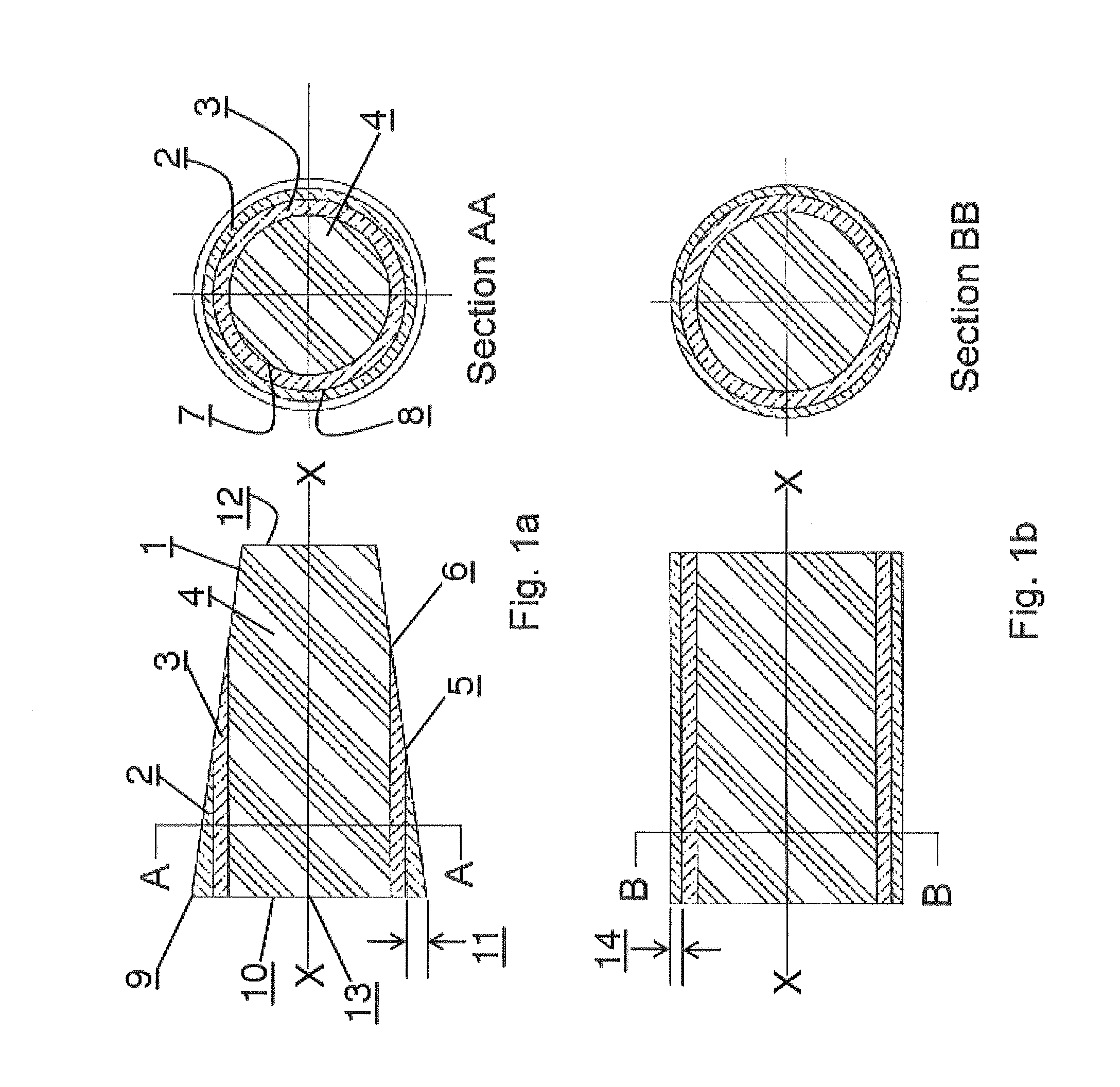
[0050]FIG. 1a provides an illustration for description of the principle of operation of the devices covered in this invention. A chamber of essentially frusto-conical shape 1, contains a mixture of several liquids of differing densities, and rotates about the longitudinal axis XX. The liquids 2, 3, and 4 separate into radially distinct layers as shown in section AA. The taper is beneficial in several ways, first it allows a small volume of liquid to offer a large radial depth (as shown at 11) compared with the radial depth the same volume would have if distributed over the whole length of a right circular cylinder of similar dimensions, see FIG. 1b at 14. Second, the taper provides a component of radial acceleration force that helps to scour the outer liquid constituent towards a port 9 placed at the larger cone diameter. Third, the taper also allows visualization of the constituent boundaries as axial locations such as 5 and 6 instead of radial locations such as 7 and 8 in some of ...


PUM

PropertyMeasurementUnit
volumeaaaaaaaaaa
diameteraaaaaaaaaa
diameteraaaaaaaaaa

Abstract

Centrifuges are useful to, among other things, remove red blood cells from whole blood and retain platelets and other factors in a reduced volume of plasma. Platelet rich plasma (PRP) and or platelet poor plasma (PPP) can be obtained rapidly and is ready for immediate injection into the host. Embodiments may include valves, operated manually or automatically, to open ports that discharge the excess red blood cells and the excess plasma into separate receivers while retaining the platelets and other factors in the centrifuge chamber. High speeds used allow simple and small embodiments to be used at the patient's side during surgical procedures. The embodiments can also be used for the separation of liquids or slurries in other fields such as, for example, the separation of pigments or lubricants.

Description

CROSS REFERENCE TO RELATED APPLICATIONS[0001]This application is a Continuation-In-Part Application of our earlier filed U.S. patent application Ser. No. 12 / 949,781 on Nov. 19, 2010, entitled Centrifuge, which is assigned to the same assignee as this invention and whose disclosures are incorporated by reference herein.BACKGROUND OF THE INVENTION[0002]1. Field of the Invention[0003]The present invention pertains to centrifuges.[0004]2. Discussion of Related Art[0005]Fluids, such as whole blood or various other biological fluids are suspensions and can be separated into their constituent parts or fractions. For example, whole blood comprises four main fractions, red blood cells, white blood cells, platelets and plasma, that can be separated based on their different densities in a device such as a centrifuge. An anti-coagulated whole blood sample may be placed in a test tube, or other similar device, which is then spun in a centrifuge at a specified speed. The generated centrifugal for...

Claims


Application Information

Patent Timeline
Patent Type & Authority Applications(United States)
IPC IPC(8): B04B1/06B04B7/08B01D21/26B04B7/16B04B11/05B04B11/00B04B15/00B04B7/12
CPCA61M1/3693B01D21/245B01D21/262B01D21/34B01D2221/10B04B5/0407B04B5/0442B04B7/08B04B11/04B04B2005/0485B04B1/02A61M1/3696B04B15/08B04B9/10
Inventor NASH, JOHN E.FISHER, WILLIAM T.
Owner DSM IP ASSETS BV
Why Eureka
Try Eureka