
Device and method for controlling secondary battery

a secondary battery and battery technology, applied in secondary cell servicing/maintenance, batteries, instruments, etc., can solve the problems of data loss, limited capacity of such a secondary battery, and inability to accurately calculate the remaining battery capacity, so as to accurately detect the remaining capacity of the secondary battery

Active Publication Date: 2012-05-24
PANASONIC CORP
View PDF15 Cites 59 Cited by
  • Summary
  • Abstract
  • Description
  • Claims
  • Application Information

AI Technical Summary

Benefits of technology

[0011]An object of the present invention is to provide a device and method for controlling a secondary battery, where the device and method are used for electronic devices having a power-saving mode, and can accurately detect the remaining capacity of the secondary battery while taking advantage of the effect of the power-saving mode. Another object of the present invention is to provide a device and method for controlling two or more secondary batteries, where the device and method are used for electronic devices each having two or more secondary batteries, and can appropriately perform switching between the secondary batteries during the power-saving mode.
[0015]The secondary battery control device and control method according to the present invention can accurately detect a remaining capacity of a secondary battery while taking advantage of the effect of the power-saving mode. Further, in an electronic device having two or more secondary batteries, switching between the secondary batteries can be appropriately performed during the power-saving mode.

Problems solved by technology

The capacity of such a secondary battery, which is chargeable by single charging, is limited.
Thus, the techniques disclosed in Patent Literatures 1 to 3 cannot accurately calculate the remaining battery capacity while taking advantage of the effect of the power-saving mode.
If the remaining battery capacity cannot be accurately calculated during the power-saving mode, the following problem may occur.
This situation might cause a serious problem such as data loss.
In the case of a notebook PC having two batteries, the following problem may occur.
In such case, since power cannot be supplied from the fully-discharged battery to the power-supply control microcomputer, the one battery cannot be switched to the other battery.
Although the notebook PC has the two batteries and the other battery has a remaining capacity, battery switching cannot be performed.

Method used


Image

  • Device and method for controlling secondary battery
  • Device and method for controlling secondary battery
  • Device and method for controlling secondary battery

Examples


embodiment 1

[0024]Hereinafter, a battery control device according to Embodiment 1 of the present invention will be described with reference to FIGS. 1 to 4.

[0025](Structure)

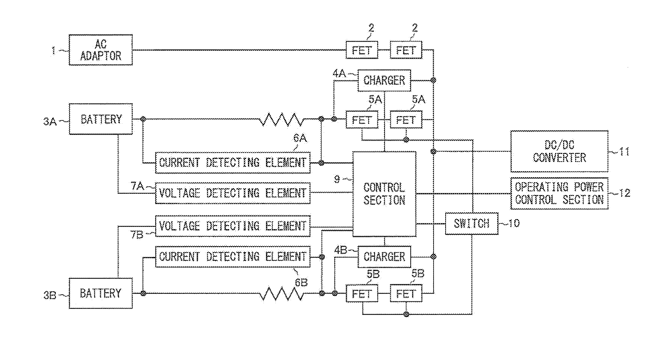
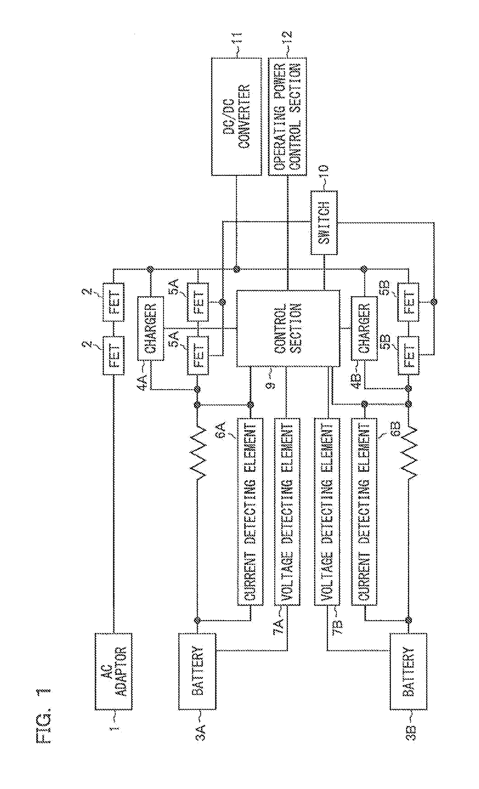
[0026]FIG. 1 is a block diagram illustrating an exemplary schematic structure of the battery control device according to Embodiment 1. The battery control device controls two batteries incorporated in a notebook PC as an example of an electronic device. The battery control device of Embodiment 1 uses two batteries, i.e., a battery 3A as a first battery and a battery 3B as a second battery. These batteries have the same rating. However, the application of the present invention is not limited to a notebook PC having two batteries. The present invention is applicable to other electronic devices, such as PDAs (Personal Digital Assistances) and mobile phones, each having two batteries. In any case, the two batteries may have different ratings. The number of batteries may be one or more than two. Each of the batteries may be provi...

embodiment 2

[0063]Hereinafter, a battery control device according to Embodiment 2 of the present invention will be described with reference to FIGS. 5 and 6. In the following description, the description of the same components as those of Embodiment 1 is not repeated. It should be noted that the battery control device according to Embodiment 2 controls two or more batteries.

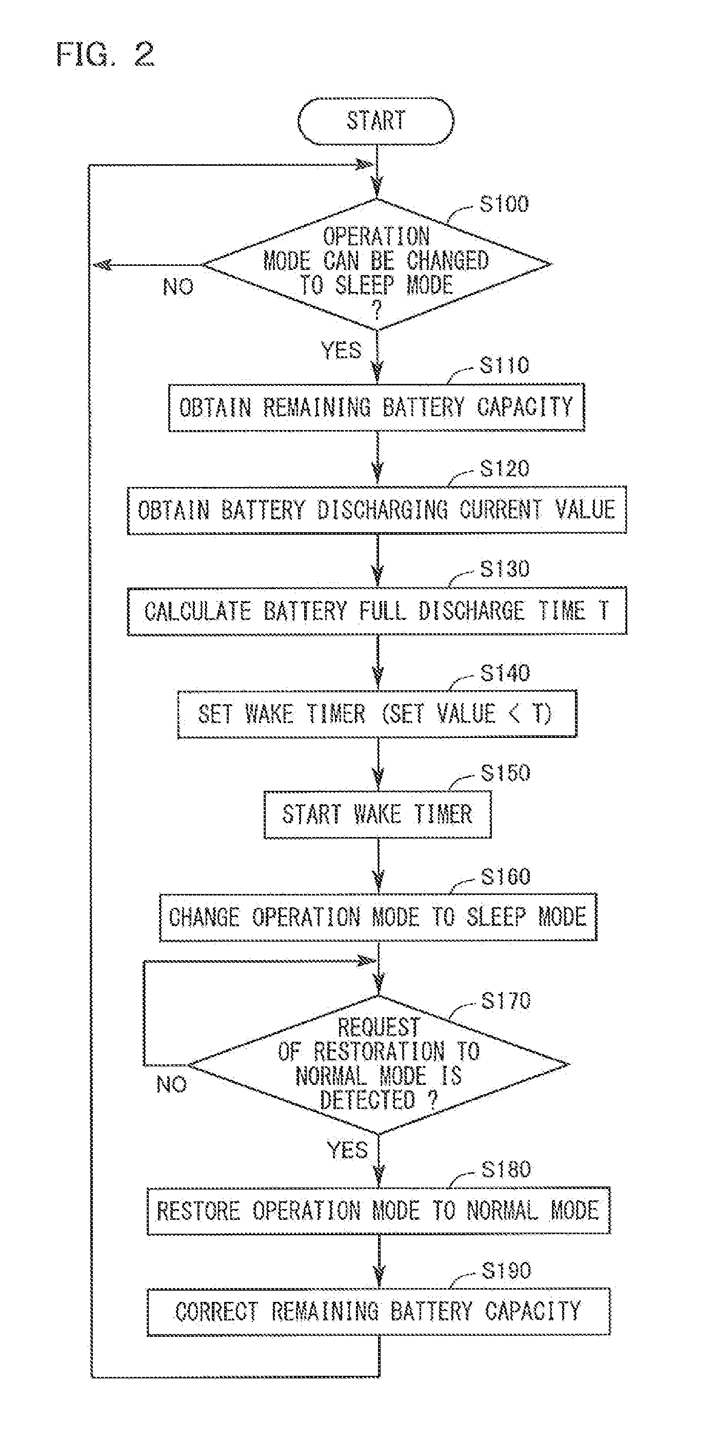
[0064]The hardware structure of the battery control device according to Embodiment 2 is identical to that shown in FIG. 1. In this embodiment, the control section 9 executes a battery switching process, in addition to the remaining battery capacity detecting process described for Embodiment 1. The control flow of the battery switching process will be described with reference to FIG. 5. The processes at S100 to S190 in FIG. 5 are identical to those in FIG. 2.

[0065]In S200, the control section 9 determines whether the remaining battery capacity is lower than a switching threshold. When it is determined that the remaining batte...


PUM


Abstract

A secondary battery control device having a sleep mode includes a current detection element for detecting a charging / discharging current value of a battery, a voltage detection element for detecting an open-circuit voltage value of the battery, and a control section for calculating the remaining capacity of the battery based on the detected values. When the control section enters the sleep mode, the control section sets, in a wake timer, based on the remaining battery capacity and the discharging current value at this time, an amount of time required for the remaining battery capacity to reach a predetermined value (about 5%), as an amount of time required for the control section to be restored to a normal mode. When the set amount of time has passed, the control section is restored to the normal mode, and corrects the remaining battery capacity to obtain an accurate remaining battery capacity.

Description

CROSS REFERENCE TO RELATED APPLICATION[0001]The disclosure of Japanese Patent Application No. 2010-257802, filed Nov. 18, 2010, is incorporated herein by reference.BACKGROUND OF THE INVENTION[0002]1. Field of the Invention[0003]The present invention relates to a device and method for controlling a secondary battery, wherein the device and method are used for an electronic device that uses, as an operation power supply, a secondary battery (sometimes referred to simply as “battery”, hereinafter) such as a lithium ion battery, and accurately detect the remaining capacity of the secondary battery when the electronic device enters a power-saving mode (sometimes referred to simply as “sleep mode”, hereinafter).[0004]2. Description of the Background Art[0005]Secondary batteries are popular as power supplies for supplying power to portable electronic devices such as mobile phones, digital cameras, and notebook PCs. The capacity of such a secondary battery, which is chargeable by single cha...

Claims


Application Information

Patent Timeline
Patent Type & Authority Applications(United States)
IPC IPC(8): G06F1/00
CPCH02J7/0021H02J7/0047H02J9/005H02J2007/005H02J7/0024Y02B60/1292H01M10/44H01M10/48G06F1/3212H01M10/00G01R31/36H01M10/441H01M10/482H01M2220/30H02J7/0048Y02D10/00Y02E60/10
Inventor KAMIJIMA, JUNYA
Owner PANASONIC CORP
Learn More