Friction damping bolt connection for a wind tower lattice structure

a technology of bolt connection and wind turbine, which is applied in the direction of buildings, towers, buildings, etc., can solve the problems of adding additional vibration damping into the system, and achieve the effect of increasing movement and flexibility

Inactive Publication Date: 2012-05-31
GENERAL ELECTRIC CO
View PDF7 Cites 14 Cited by
  • Summary
  • Abstract
  • Description
  • Claims
  • Application Information

AI Technical Summary

Benefits of technology

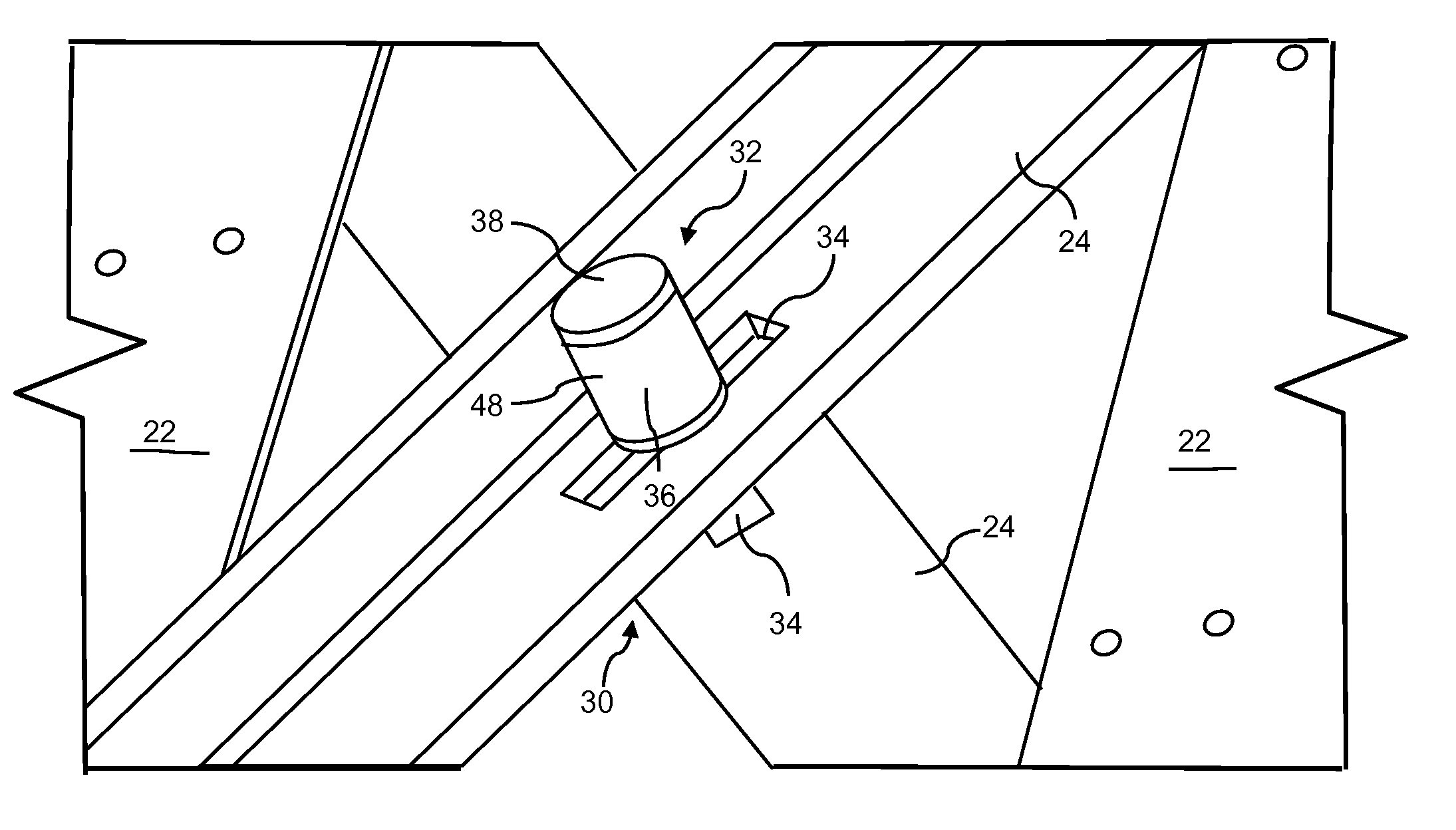
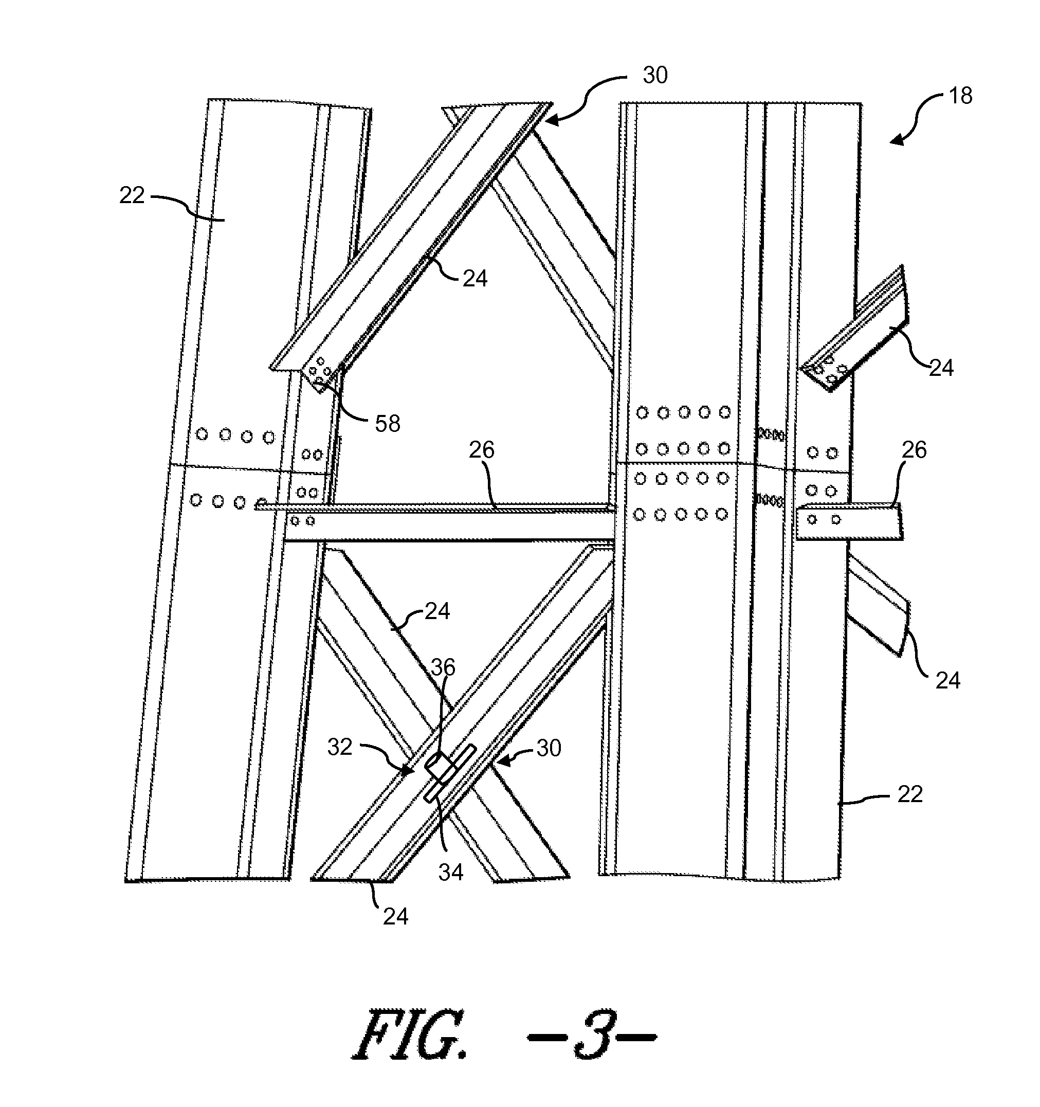
[0009]It certain embodiments, a friction disk is disposed between facing surface of the cross braces at the intersection point. The friction disk is formed from a friction-enhancing material that increases the friction of the relative sliding movement between the facing surfaces of the cross braces, thus adding additional vibration damping into the system.
[0013]In another embodiment, increased movement and flexibility between the cross braces and vertical leg members may be desired, and the longitudinal ends of the cross braces are rotationally fixed to the vertical leg members. For example, a single bolt, rivet, or the like may be used to attach the members and may define a pivot point for relative (limited) rotational motion between the cross brace and vertical leg member.

Problems solved by technology

The friction disk is formed from a friction-enhancing material that increases the friction of the relative sliding movement between the facing surfaces of the cross braces, thus adding additional vibration damping into the system.

Method used


Image

  • Friction damping bolt connection for a wind tower lattice structure
  • Friction damping bolt connection for a wind tower lattice structure
  • Friction damping bolt connection for a wind tower lattice structure

Examples


Embodiment Construction

[0025]Reference now will be made in detail to embodiments of the invention, one or more examples of which are illustrated in the drawings. Each example is provided by way of explanation of the invention, not limitation of the invention. In fact, it will be apparent to those skilled in the art that various modifications and variations can be made in the present invention without departing from the scope or spirit of the invention. For instance, features illustrated or described as part of one embodiment can be used with another embodiment to yield a still further embodiment. Thus, it is intended that the present invention covers such modifications and variations as come within the scope of the appended claims and their equivalents.

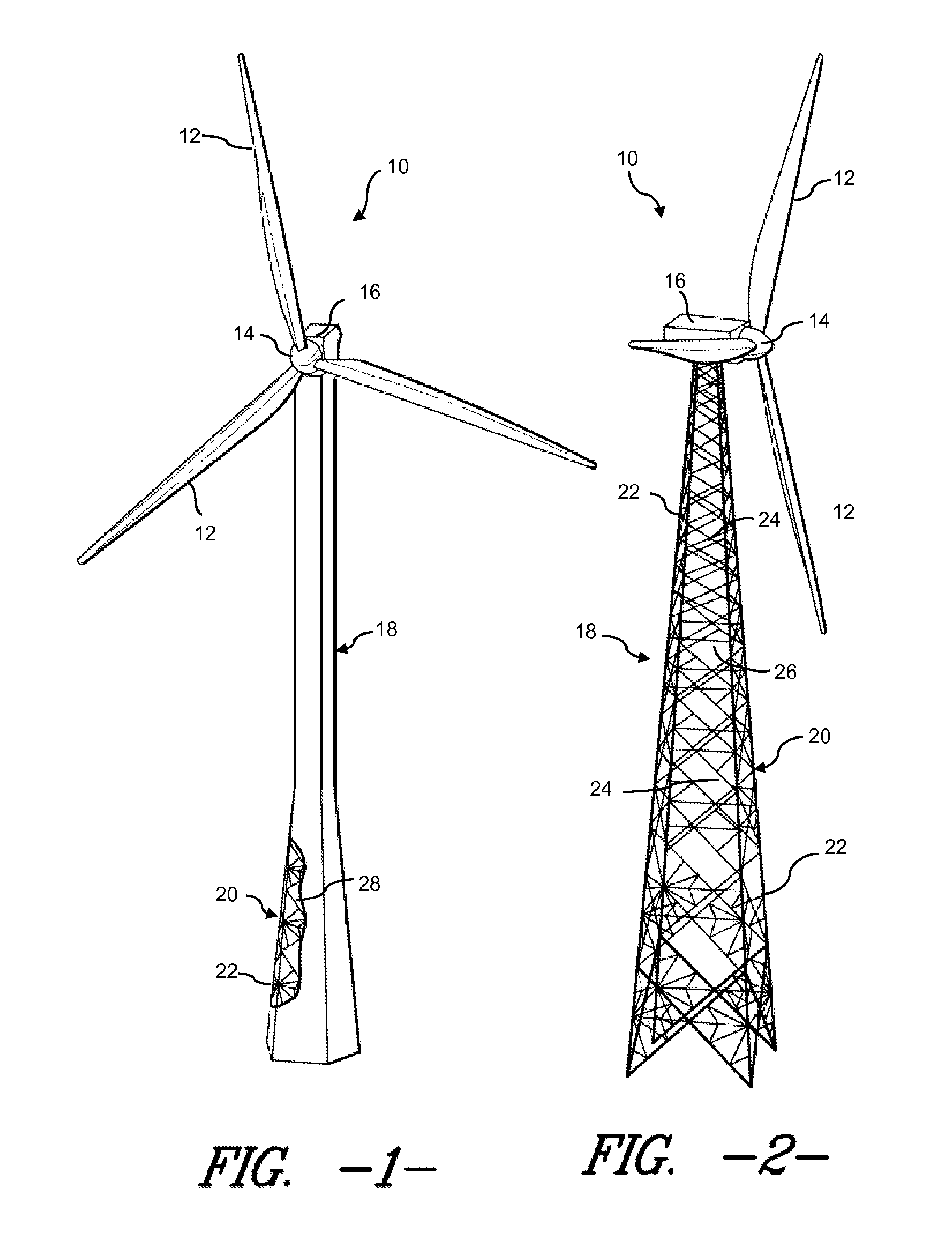
[0026]FIGS. 1 and 2 are perspective views of exemplary wind turbines 10. Each wind turbine 10 includes a plurality of blades 12 mounted to a rotor hub 14, which in turn is rotationally supported any manner of power generation components housed within a nace...


PUM


Abstract

A wind turbine lattice tower structure includes a plurality of structural members connected together to define an open lattice tower, with the structural members including vertical leg members and diagonal braces extending between the vertical leg members. Pairs of the diagonal braces form cross braces having an intersection point therebetween. A damping bolt connection assembly is provides at the intersection point of the cross braces and is configured to attach the cross braces together at the intersection point while providing for relative movement of each individual cross brace along a defined longitudinal section of the other respective cross brace.

Description

FIELD OF THE INVENTION[0001]The present invention relates generally to wind turbine tower structures, and more particularly to an improved bolt connection for lattice tower structures.BACKGROUND OF THE INVENTION[0002]Conventional wind turbine towers typically include a tubular pole or a lattice structure to support a wind turbine at a considerable height to capture wind energy. The tubular pole configuration is relatively more simple and easier to assemble than the lattice structure. However, tubular poles use more steel than the lattice structure, resulting in a cost disadvantage with rising prices of steel.[0003]The lattice structure towers use significantly less steel and other materials as compared to conventional tubular towers (generally about 30%-40% less). The lattice towers, however, lack the torsional rigidity of the tubular constructions and this decreased torsional stiffness potentially induces vibrations and stresses in the tower that must be compensated for.[0004]It is...

Claims


Application Information

Patent Timeline
Patent Type & Authority Applications(United States)
IPC IPC(8): E04B1/38E04B1/19E04H12/00
CPCE04B2001/2439Y02E10/728E04H12/10
Inventor FANG, BIAOLUO, HUAGENG
Owner GENERAL ELECTRIC CO
Why Eureka
Try Eureka