

Variable capacity compressor
- Summary
- Abstract
- Description
- Claims
- Application Information
AI Technical Summary
Benefits of technology
Problems solved by technology
Method used
Image

Examples
Embodiment Construction
[0036]A variable capacity compressor of an embodiment of the present invention will be described with reference to the accompanying drawings.
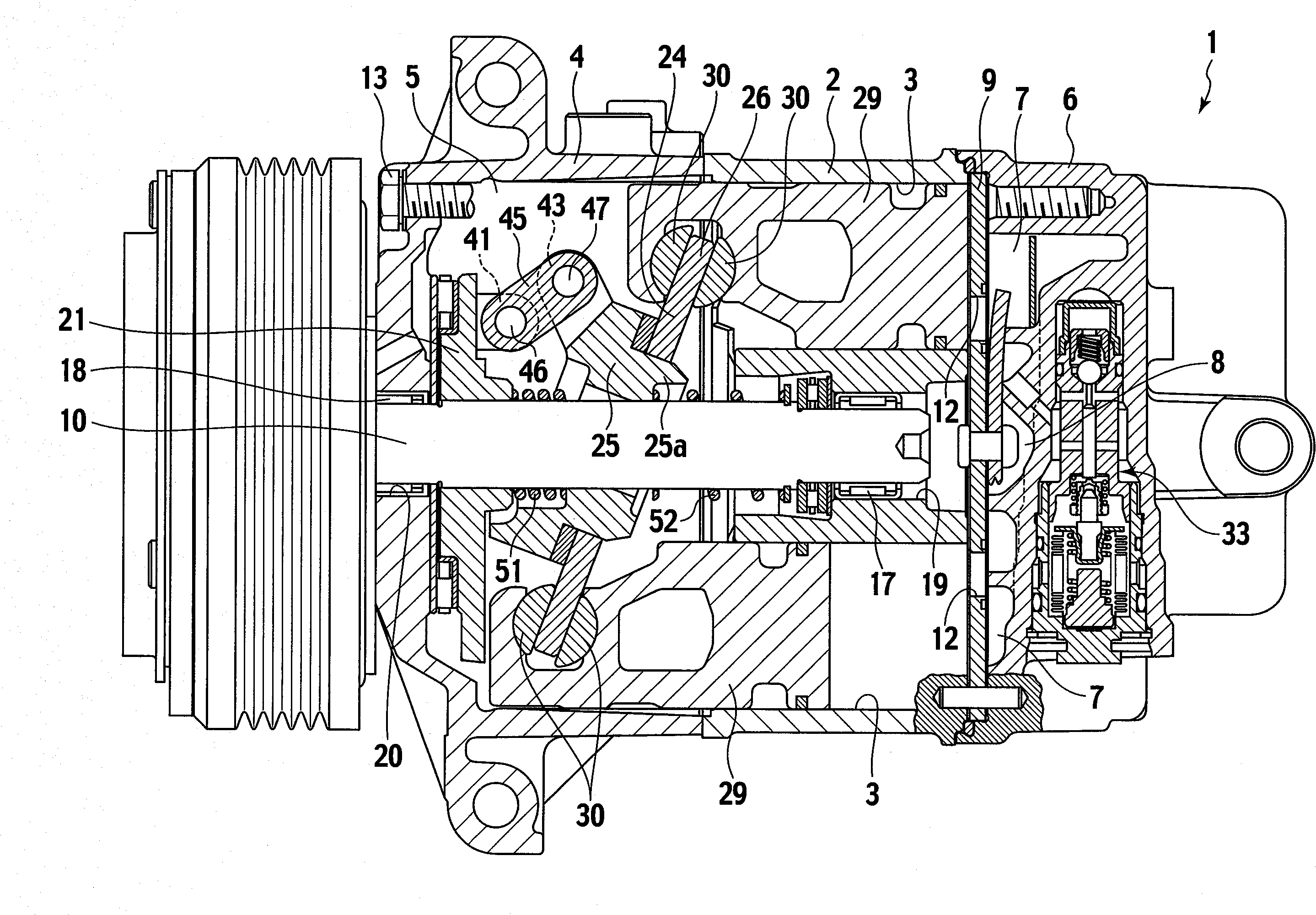
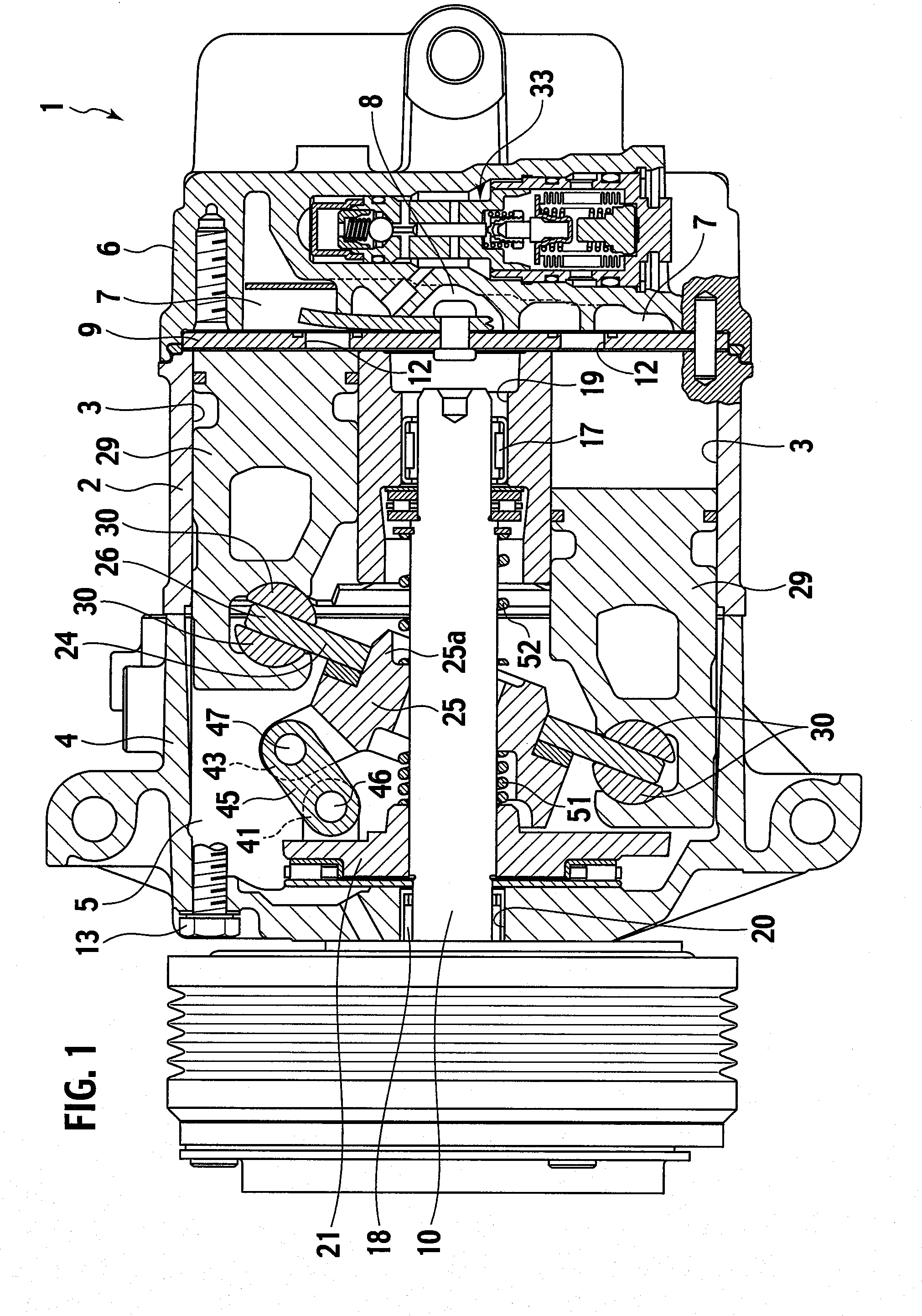
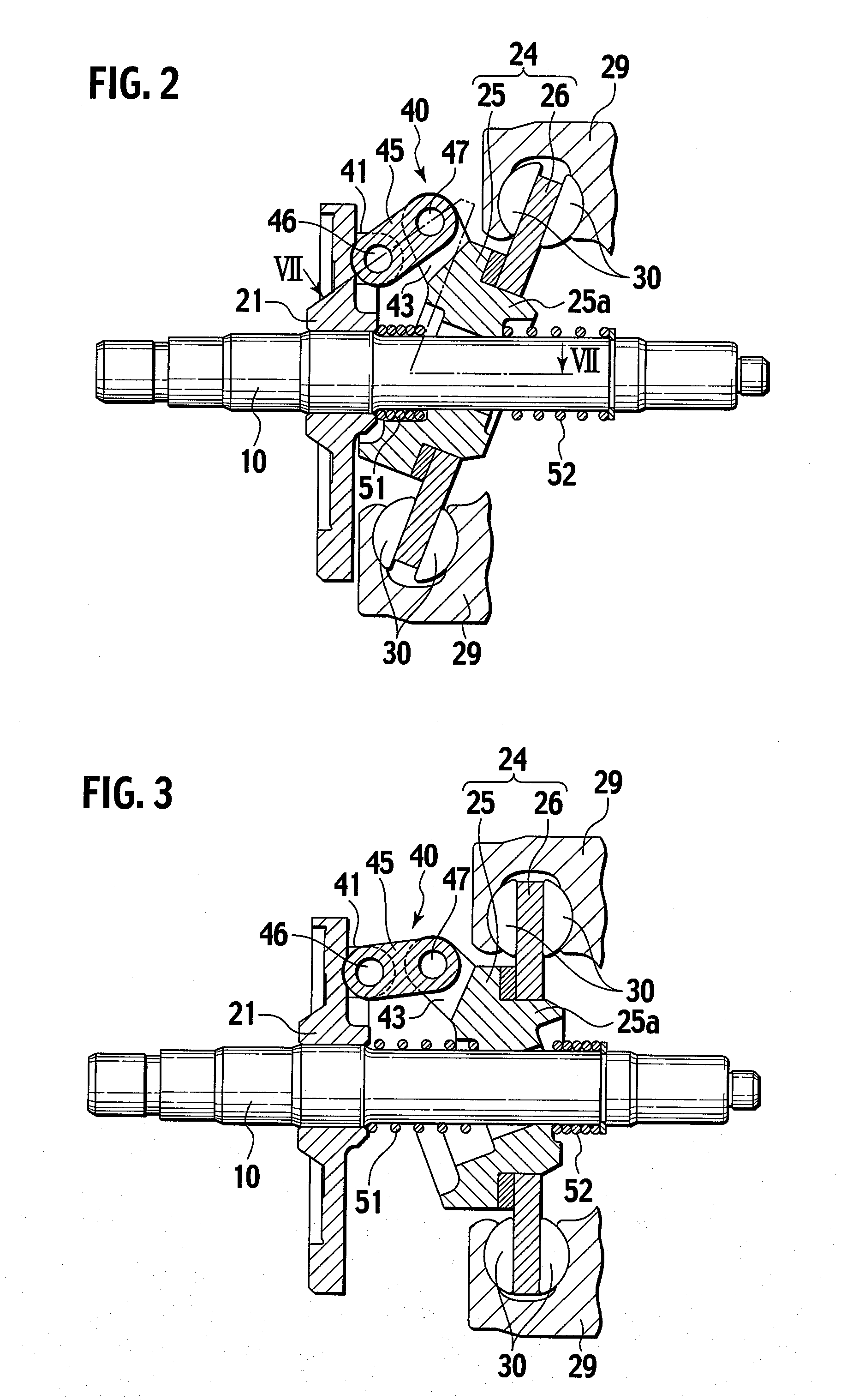
[0037]FIG. 1 is a cross-sectional view of the entire variable capacity compressor, FIG. 2 shows an inclination of a swash plate in a full stroke condition, and FIG. 3 shows an inclination of the swash plate in a no-stroke condition.
[0038]As shown in FIG. 1, the variable capacity compressor 1 includes a cylinder block 2 having a plurality of cylinder bores 3 (FIG. 2) placed evenly spaced apart in a circumferential direction, a front housing 4 attached to a front end of the cylinder block 2 and having a crank chamber 5 therein, and a rear housing 6 attached to a rear end of the cylinder block 2 via a valve plate 9 and having a suction chamber 7 and a discharge chamber 8 therein. The cylinder block 2, the front housing 4, and the rear housing 6 are fixedly connected to one another by a plurality of bolts 13 so as to make up a housing of the compre...
PUM
 Abstract
Description
Claims
Application Information