Run flat tire

a technology of run-flat tires and treads, which is applied in the direction of pneumatic tyre reinforcements, tire beads, vehicle components, etc., can solve the problems of reducing the durability of run-flat tires, reducing the service life of run-flat tires, and suppressing the buckling of treads, so as to improve the service life and improve the service life. the effect of durability

Inactive Publication Date: 2012-05-31
THE YOKOHAMA RUBBER CO LTD
View PDF0 Cites 13 Cited by
  • Summary
  • Abstract
  • Description
  • Claims
  • Application Information

AI Technical Summary

Benefits of technology

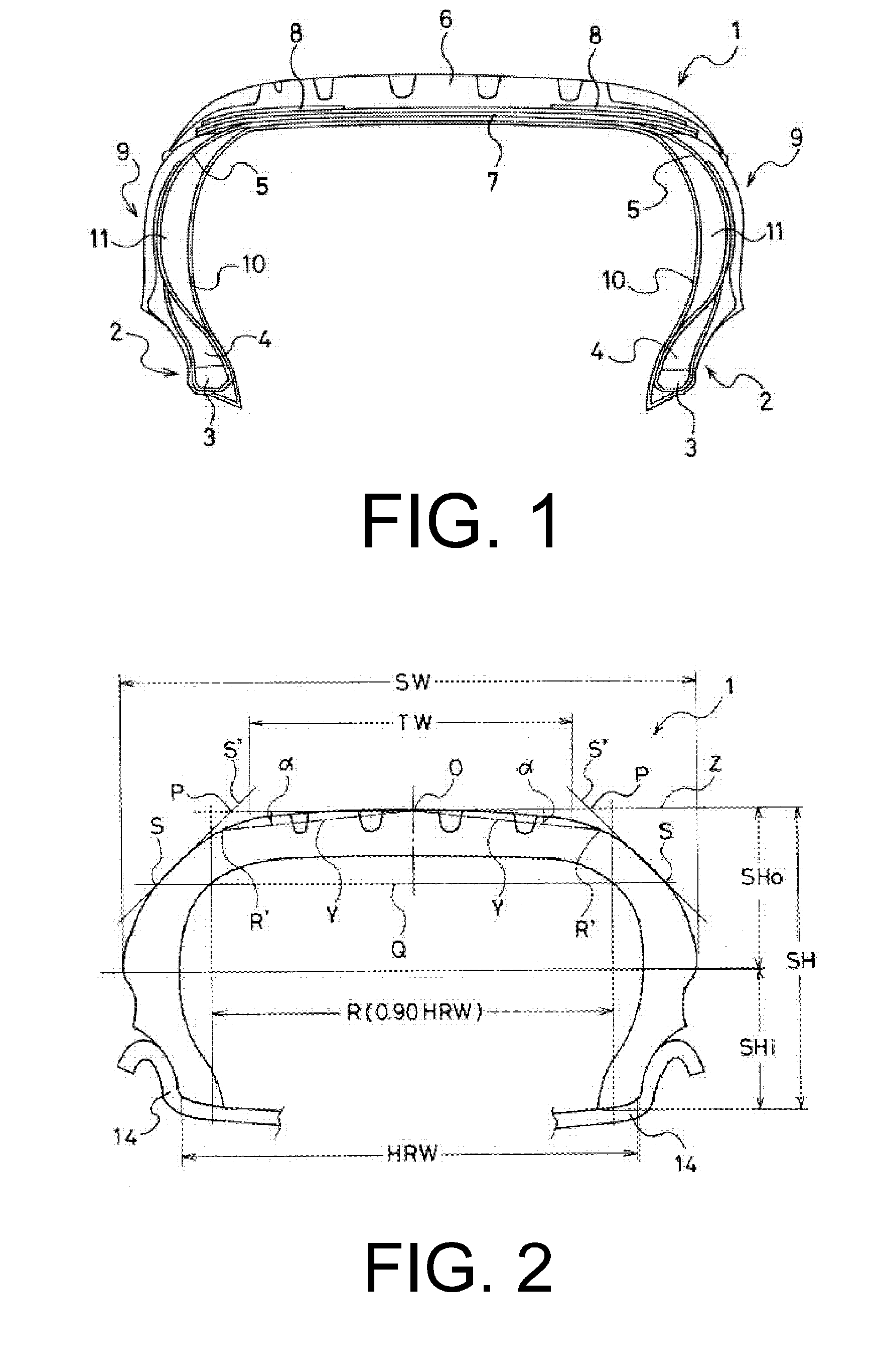
[0015]According to the present technology, a ratio SHi / SHo between a tire cross-sectional height SHi on an inner side in the tire radial direction and a tire cross-sectional height SHo on an outer side in the tire radial direction, demarcated by a maximum tire width position when the run flat tire is inflated to a certain air pressure, is from 0.7 to 0.9; and the maximum tire width position is located on the bead portion side. Moreover, an intersection P of a line tangent to an intersection S of a straight line Q in a tire axial direction passing through a midpoint of the tire cross-sectional height SHo and a tire outer wall and an tire external diameter line Z is positioned more to a tire equatorial plane side than a region R that corresponds to 90% of a rim width HRW of the standard rim having the tire equatorial plane as a center. Thereby, an angle formed by the tire outer wall in an upper region of the side wall portion is set so as to be gradual in the tire axial direction. Additionally, an angle α of a straight line connecting, in the tread surface, a point O on the tire equatorial plane and a point R′ on a shoulder side corresponding to 110% of a tire ground contact width TW having the tire equatorial plane as a center, with respect to the tire axial direction, is set to a large angle (from 7.5° to 10°). Therefore, a cross-sectional shape of the tread surface is formed into a curved surface. As a result of the synergy achieved therefrom, even if the inflated air pressure declines, buckling of the tread portion can be prevented and excellent durability can be ensured while enhancing riding comfort when regular traveling to a high level.
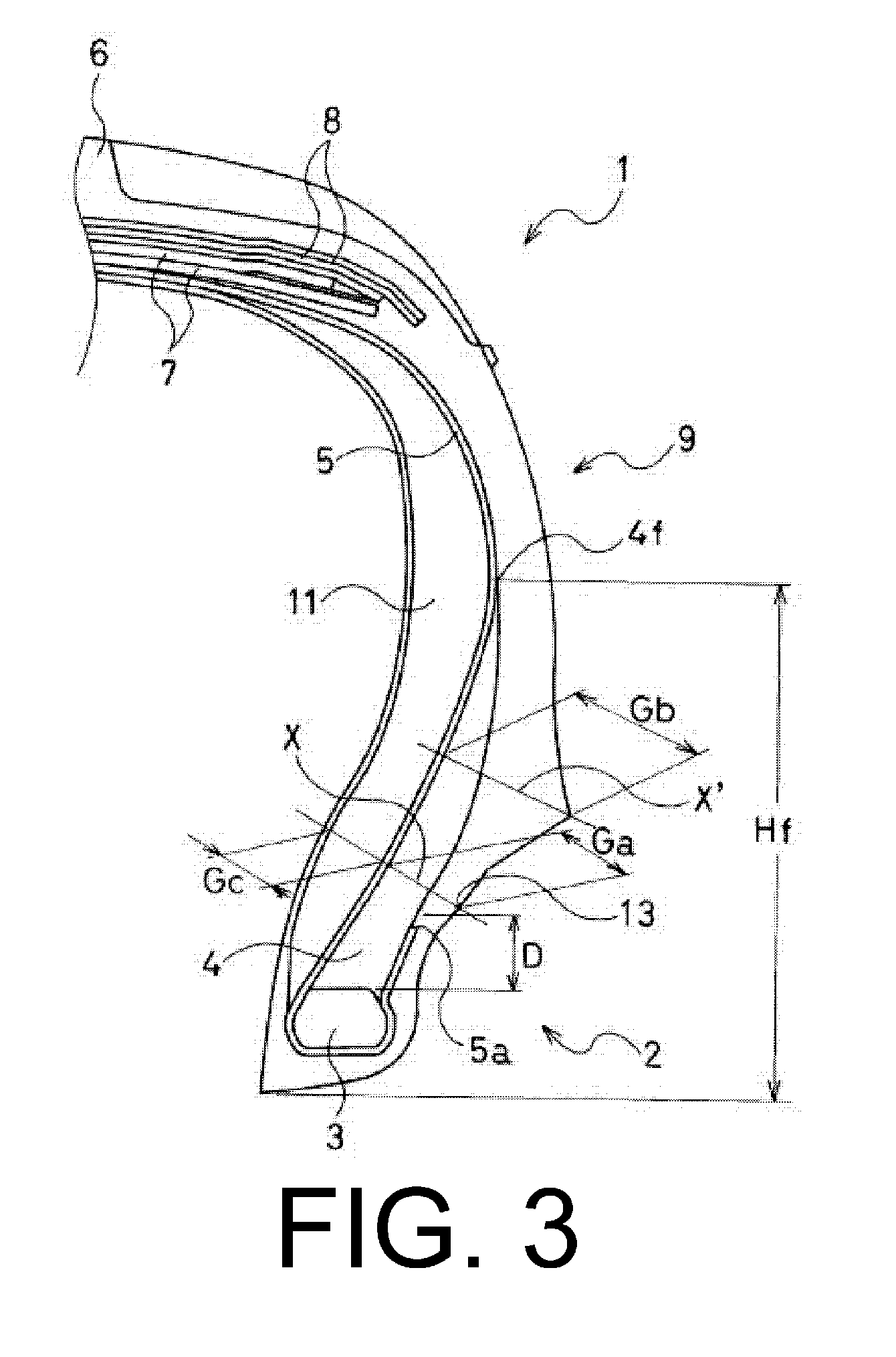
[0016]Moreover, a folded up end of the carcass layer is positioned in a lower region within 15 mm from an outer peripheral surface of the bead core toward the outer side in the tire radial direction and a height Hf of an outer peripheral edge of the bead filler is configured to be from 40% to 70% of a tire cross-section height SH. Therefore, rubber thickness between the rim flange and the carcass layer, in the vicinity of the area that is subjected to the greatest contact pressure with the rim, can be ensured without severely increasing the rubber thickness of the side wall portion. As a result, breakdowns of the carcass layer in the vicinity of the rim cushion when run-flat traveling can be effectively suppressed and, at the same time, due to the folded up end of the carcass layer being distanced from the portion where the greatest deflection occurs, failures caused by cracks from the folded up end of the carcass layer can be effectively suppressed.
[0017]Additionally, the relationship between the rubber thickness Ga, taken on the line normal to the rim line between the carcass layer and the outer wall surface of the side wall portion, and the maximum rubber thickness Gb, taken on the line normal to the carcass layer between the carcass layer and the outer wall surface of the side wall portion, is such that each thickness is set within a predetermined range; and a ratio of variation in the rubber thickness in the tire radial direction on the outer side of the carcass layer is restricted. As a result, localized, concentrated stress caused by contact pressure with the rim is relieved, which leads to separation breakdowns of the rubber in the vicinity of the rim cushion being suppressed when run-flat traveling. At the same time, rubber thickness in the upper region of the bead portion being ensured and, therefore, riding comfort when regular traveling can be enhanced.
[0018]Furthermore, a large rubber thickness Gc taken on the line normal to the rim line between the carcass layer and the tire inner wall surface is ensured, and the rubber thickness Gc is set so as to be close to the rubber thickness Ga described above. As a result, it is possible to relieve shearing stress acting between main body side and the folded over side of the carcass layer, which leads to separation breakdowns therebetween being suppressed. Particularly, durability when run-flat traveling can be enhanced, and, at the same time, riding comfort when regular traveling can be enhanced due to rubber thickness being maintained in regions where great deformation occurs due to input from the rim.

Problems solved by technology

However, when only these sorts of technologies are applied, there are problems in that the degree to which excellent run flat durability can be ensured is limited and riding comfort when regular traveling is significantly worsened due to an increase in side stiffness.
Particularly, when the tire cross-sectional height reaches a certain height, failures when run-flat traveling consist mainly of breakdowns in the vicinity of the rim cushion near the bead portion.
However, when inflated air pressure declines, both of these proposals experience difficulty in suppressing the buckling of the tread portion and are limited as to effectiveness in enhancing run flat durability and, at the same time, do not directly lead to improvement effects in riding comfort when regular traveling.
Therefore, neither proposal provides technology that can sufficiently satisfy the demands for both run flat durability and riding comfort.
As a result, localized, concentrated stress caused by contact pressure with the rim is relieved, which leads to separation breakdowns of the rubber in the vicinity of the rim cushion being suppressed when run-flat traveling.

Method used


Image

  • Run flat tire
  • Run flat tire
  • Run flat tire

Examples


examples

[0050]A conventional tire (Conventional Example) and present technology tires (Working Examples 1 to 5) were manufactured having a common tire size of 245 / 45R17. A position of the intersection P with respect to the line of demarcation in the region that corresponds to 90% of the rim width (“Intersection P position” in Table 1) after inflation to an air pressure of 180 kPa, an angle α of a straight line Y with respect to the tire axial direction (“Angle α” in Table 1), a distance in the tire radial direction of the folded up end of the carcass layer from the bead core outer peripheral surface (“Carcass folded up end to bead core outer peripheral surface” in Table 1), a height (Hf / SH) of the outer peripheral edge of the bead filler, a ratio of the rubber thickness Ga with respect to the rubber thickness Gb, and a ratio of the rubber thickness Gc with respect to the rubber thickness Ga were each varied as shown in Table 1.

[0051]Note that in each of the tires, rayon fiber cord was used ...


PUM


Abstract

A run flat tire where: the ratio of the cross-sectional height on the inner side in the radial direction to the cross-sectional height on the outer side in the radial direction, having the maximum tire width in a state inflated to an air pressure as a boundary; the inclination angle of the outer wall in the upper region of the side wall portion; the curving form of the tread surface; the position of the carcass folded over end; the height of the bead filler; the relationship between the thickness of the outer side rubber taken on a line normal to the rim line and the maximum thickness of the outer side rubber in an upper region of the bead portion; and the relationship of the thickness of the inner side rubber and the thickness of the outer side rubber taken on a line normal to the rim line are stipulated.

Description

PRIORITY CLAIM[0001]Priority is claimed to Japan Patent Application Serial No. 2010-264858 filed on Nov. 29, 2010.BACKGROUND[0002]1. Technical Field[0003]The present technology relates to a run flat tire, and particularly relates to a run flat tire configured so as to have both durability when run-flat traveling and riding comfort when regular traveling.[0004]2. Related Art[0005]Generally, in run flat tires provided with a side reinforcing layer having a falcated cross-section on an inner surface side of a side wall portion, methods such as increasing a thickness of the side reinforcing layer and using a rubber with a high hardness have been used in order to ensure durability when run-flat traveling. However, when only these sorts of technologies are applied, there are problems in that the degree to which excellent run flat durability can be ensured is limited and riding comfort when regular traveling is significantly worsened due to an increase in side stiffness.[0006]Particularly,...

Claims


Application Information

Patent Timeline
Patent Type & Authority Applications(United States)
IPC IPC(8): B60C17/00
CPCB60C17/0009B60C15/0607B60C3/04B60C2017/0072Y10T152/10837B60C2013/006B60C2013/007B60C2009/2252Y10T152/10819B60C2017/0063
Inventor HORIUCHI, KENJI
Owner THE YOKOHAMA RUBBER CO LTD
Why Eureka
Try Eureka