
Downhole tool and method

a drill pipe and tooling technology, applied in the field of drill pipe tools, can solve the problems of insufficient drill pipe weight in the string to resist the high pressure, the possibility of premature setting of the packer, and the difficulty of determining whether to use it, so as to increase the frictional engagement

Active Publication Date: 2012-05-31
M I DRILLING FLUIDS U K LTD
View PDF3 Cites 22 Cited by
  • Summary
  • Abstract
  • Description
  • Claims
  • Application Information

AI Technical Summary

Benefits of technology

[0012]A tool in accordance with embodiments disclosed herein may provide a new sub to be incorporated in a work string and operably associated with a weight-set packer tool, wherein the sub is configured to selectively and reversibly deploy anchor means when a positive test is to be conducted, wherein the various operational configurations of the sub are controlled by use of circulation fluid and circulation valve means operable by introduction of an obturator into the circulation fluid and circulating it to a seat in the sub. Circulation valves are known generally in the field and the obturator or plug which is circulated to the valve seat is commonly referred to as a “ball” because that is a commonly used form, though in fact the obturator may have other forms e.g. a dart. Thus by using pressure applied by fluid circulated from the surface above the weight-set packer, a hydraulic hold-down anchor mechanism is enabled above the packer to reduce the risk of it becoming unset during a high pressure “positive” wellbore integrity test.
[0013]One or more embodiments of the present disclosure may provide a retrievable tool which can be operated by circulation valve means to selectively deploy anchor means but retain the ability to circulate fluid for other purposes when the anchor means is not deployed. Thus provision is made also for the hydraulic hold-down anchor mechanism to be disabled by a further use of a circulation valve within the new sub.
[0023]The second inner sleeve may comprise a valve seat at a trailing end of the sleeve, which seat may be formed by a tapered reduction in diameter of the sleeve bore, in the normal forward flow direction of circulation fluid, to accommodate a larger size range of obturators than the first inner sleeve. This difference in taper size allows selective actuation of the first inner sleeve by a simple size choice of obturator to ensure that it passes through the second inner sleeve without being seated therein. The second inner sleeve may be provided with fluid by-pass channels upstream and downstream of the valve seat so that when the sleeve is axially displaced within the tubular body bore to a region of said bore that is of sufficiently greater diameter than the sleeve to form a by-pass annulus between the sleeve and tubular body sufficient to admit fluid flow, said fluid flow may pass around the captured obturator on the valve seat via said upstream channels, said by-pass annulus and said downstream channels to re-enter the sleeve bore.
[0032]In the third configuration of this embodiment of the anchor sub, a locking means provided in the anchor sub tubular body is activated to restrain the second inner sleeve from further axial displacement, thereby providing additional assurance that pressure changes within the anchor sub cannot be transmitted to the anchor means to effect unintentional deployment thereof, even if for example fluid circulation is reversed for operational reasons during a subsequent use of the work string to operate other tools downhole or to accomplish a different task or procedure in the wellbore.
[0035]In a still further aspect of embodiments disclosed herein, there is provided a method of conducting a wellbore integrity test, specifically a positive test, comprisingintroducing a tool assembly comprising a compression packer and an anchor sub operatively connected therewith on a work string to a test zone of a cased or lined wellbore,circulating an obturator to a first circulation valve means provided in the anchor sub to effect a configuration change in the anchor sub to admit fluid to anchor means therein,setting the packer by setting down weight using the work string, pressuring up with circulation fluid to effect deployment of anchor means in the anchor sub, andincreasing pressure to a value sufficient to complete a positive test.

Problems solved by technology

It is normally difficult to determine whether there are any irregularities in the well bore casing connections and cement bonds as the hydrostatic pressure created by drilling fluid within the well bore prevents well bore fluid from entering the annulus of the bore.
As many other tools are activated by rotation and indeed as the drill string itself would normally be rotated during this type of operation, it is likely that the packer would prematurely set.
In the case of a weight-set or compression packer, there may be insufficient drill pipe weight in the string to resist the high pressures developed during a positive test.

Method used


Image

  • Downhole tool and method
  • Downhole tool and method
  • Downhole tool and method

Examples


Embodiment Construction

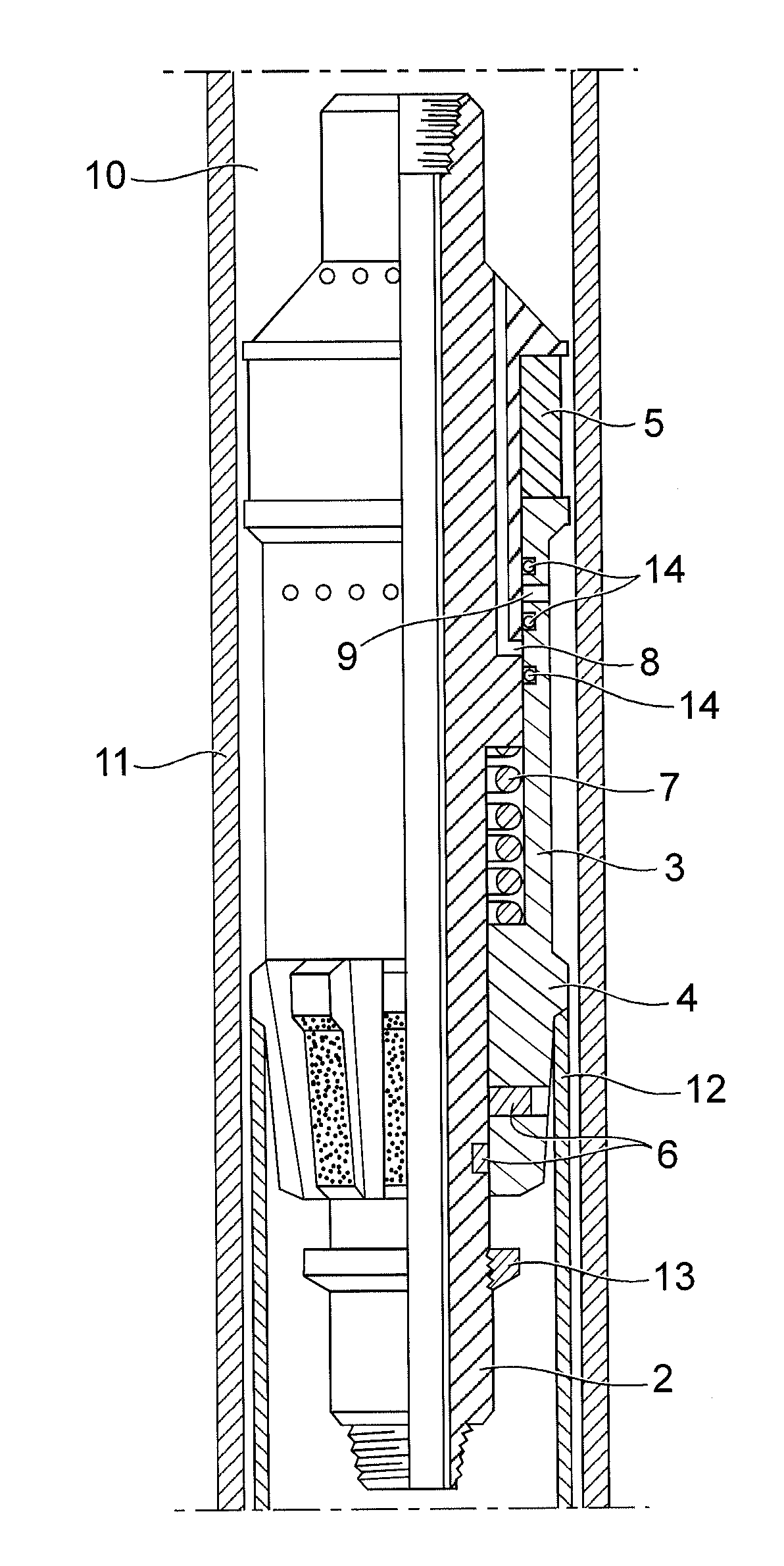
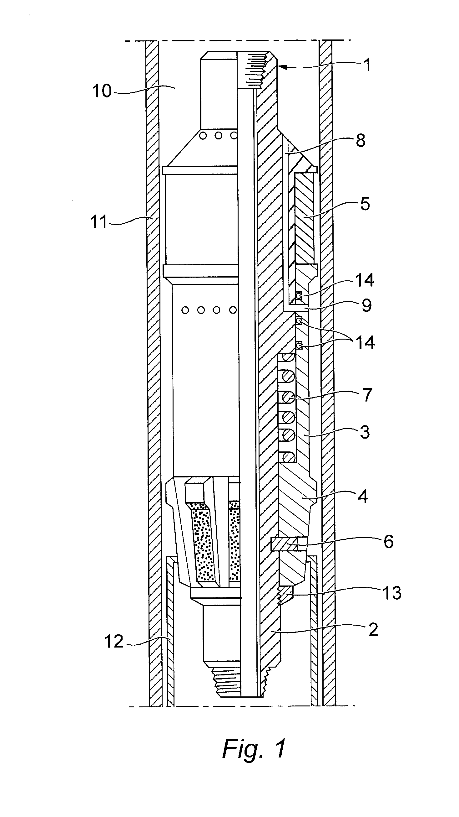
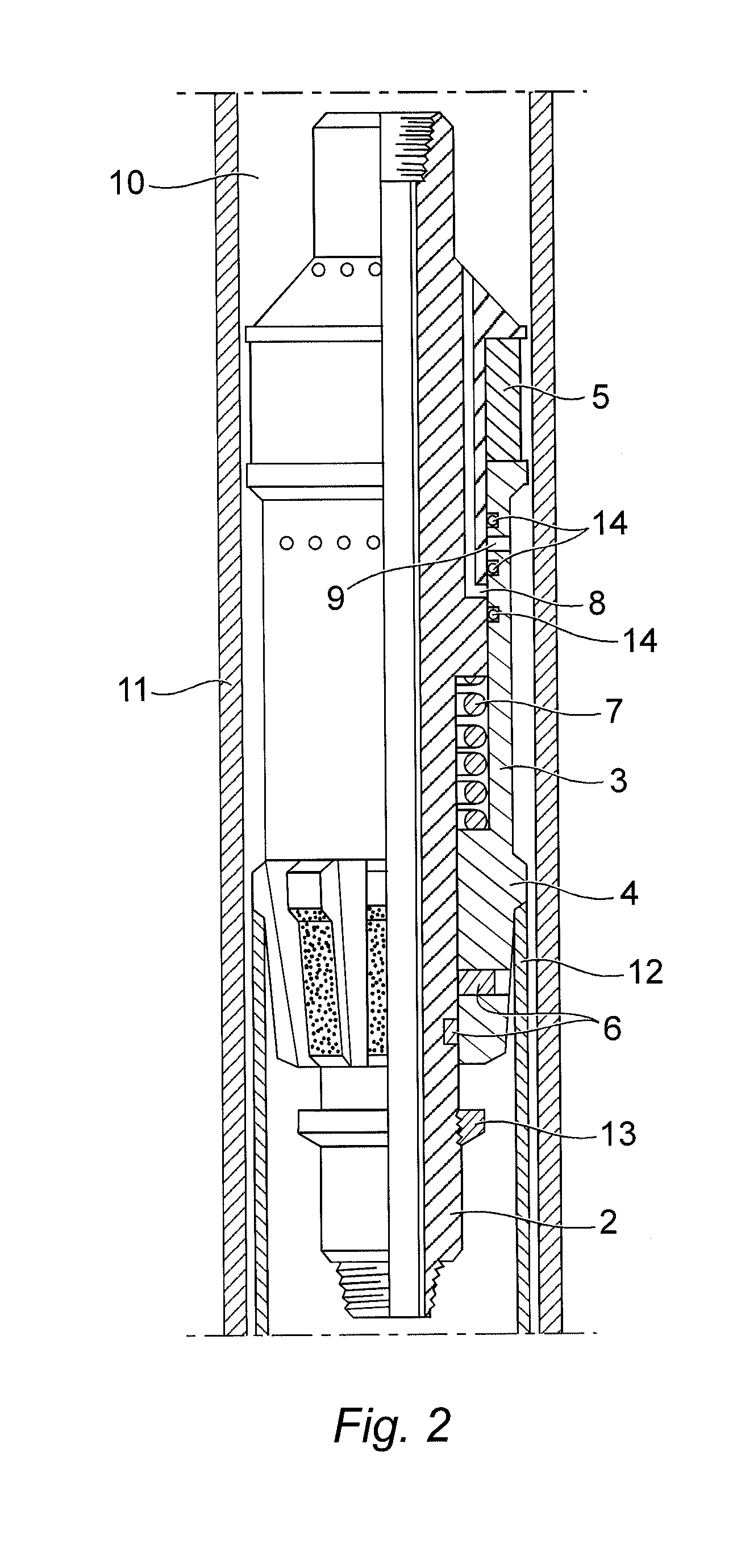
[0052]Referring firstly to FIG. 1, a compression or weight-set packer tool is generally depicted at 1 and comprises a packer body 2 and an outer compression sleeve 3 which is moveable in relation to the body 2. The body 2 is mounted on a work string (not shown), typically a drill pipe. The outer compression sleeve 3 has or is associated with a shoulder 4 which may be a liner top mill. The outer compression sleeve 3 is positioned substantially below one or more packer elements 5. The one or more packer elements 5 are typically made from a moulded rubber material. The outer sleeve 3 also has a retainer ring 13.

[0053]The outer sleeve 3 is mechanically attached to the body 2 of the tool 1 by one or more shear fasteners 6, and is biased by a spring 7. The body 2 of the tool 1 has an integral bypass channel 8 through which fluid can bypass the area around the packer elements 5, by flowing through the body 2 of the tool 1. The fluid then flows through a bypass port 9 in the sleeve 3. The i...


PUM


Abstract

A work string tool to be operably associated with a weight-set packer tool uses pressure applied by fluid circulated from the surface above the weight-set packer, to deploy a hydraulic hold-down anchor mechanism above the packer to reduce the risk of unsetting during a high pressure “positive” wellbore integrity test. An axial bore of a tool tubular body houses first and second inner sleeves, and is configured to accommodate independent axial movement of the sleeves to provide multiple fluid flowpath configurations through the tool which allow use of circulation fluid to pressure to circulate a ball obturator to a valve seat in a sleeve when a configuration change is required to deploy or release the anchor means.

Description

FIELD OF THE DISCLOSURE[0001]Embodiments disclosed herein relate to a downhole tool adapted to be attached to a workstring intended for carrying out tasks in a wellbore, suitably a drill string. More particularly, embodiments disclosed herein relate to a downhole tool adapted for use in wellbore integrity test procedures.BACKGROUND[0002]In the drilling and production of oil and gas wells, it is typical to prepare a well bore in a target oil or gas-bearing formation using a drill string which is terminated by a drill bit. The drill string is rotated to remove formation ahead of the drill bit, to drill and thus form a wellbore, and to increase the depth of the well. The drill string has an axial throughbore throughout its length which provides a fluid circulation path through the string and BHA is and back up the annulus around the string within the well bore.[0003]Drilling mud or other fluid is pumped through the drill string to cool the drill bit, and to aid the passage of drill cut...

Claims


Application Information

Patent Timeline
IPC IPC(8): E21B34/06E21B34/00
CPCE21B23/04E21B23/06E21B33/128E21B33/1285E21B47/117
Inventor TELFER, GEORGE
Owner M I DRILLING FLUIDS U K LTD
Learn More