Measuring wheel for wireline operations

Inactive Publication Date: 2005-01-06
EPSTEIN JEFFREY S
View PDF10 Cites 2 Cited by
  • Summary
  • Abstract
  • Description
  • Claims
  • Application Information

AI Technical Summary

Benefits of technology

[0021] The present invention further provides a measuring wheel for use in wireline operations. The inventive measuring wheel includes a metal wheel having a first outer radius, and a ceramic ring having an inner radius that exceeds the first outer radius by an amount in the range of 0.005 to 0.010 inches, defining a gap between the ceramic ring

Problems solved by technology

The frictional engagement between the wireline and the measuring wheel's perimeter results in rotation of the measuring wheel as the wireline is moved into and out of the wellbore by the spooling winch.
Known measuring wheels must be frequently replaced or refurbished due to wear caused by movement and rubbing of the wireline over the measuring wheel before and after frictional engagement between the two.
The calibration between the measuring wheel's outer radius and its indicated depth is very sensitive to wear: even a reduction of 0.001 inches in the radius of the measuring wheel will significantly affect the accuracy of the resulting depth indication.
Sinc

Method used


Image

  • Measuring wheel for wireline operations
  • Measuring wheel for wireline operations
  • Measuring wheel for wireline operations

Examples


Embodiment Construction

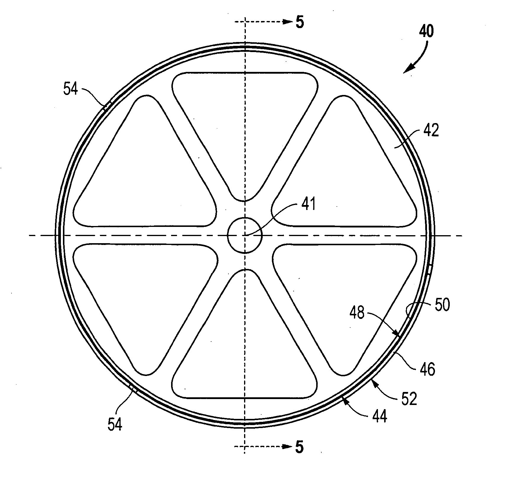
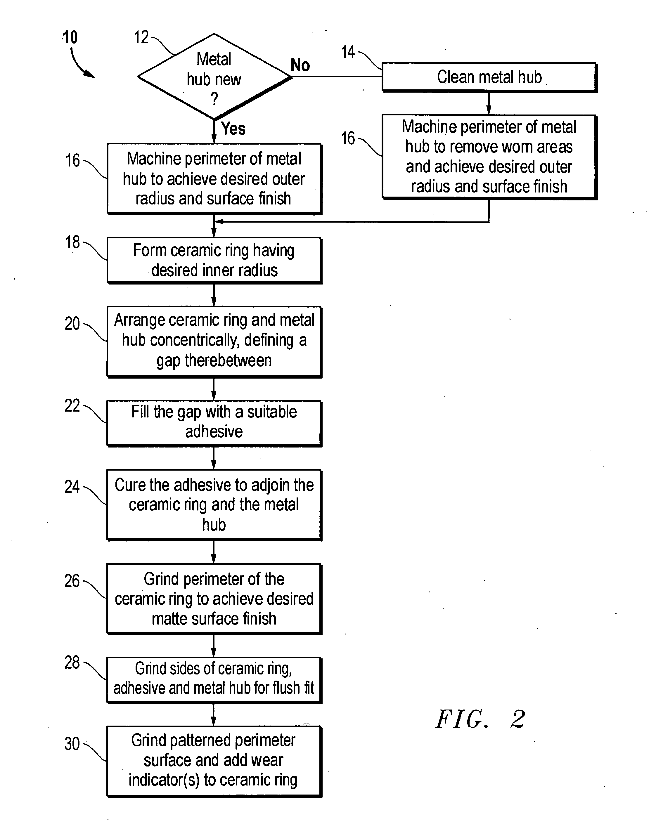
[0030] The present invention provides a method of manufacturing a measuring wheel for wireline operations. A presently preferred embodiment of the inventive method 10 will now be described with reference to the flow chart depicted in FIG. 2, as well as the various measuring wheel views of FIGS. 3-6. Because the method is applicable to new or spent measuring wheels, an initial decision point 12 requires determination of whether the metal wheel component 42 of the measuring wheel 40 is new. Metal wheels make up the entire measuring wheel in many of the present commercial offerings, and are often discarded when a radial groove or other wear depth exceeding 0.010 inches is detected. The present invention provides a means for effectively refurbishing worn or spent measuring wheels, as opposed to merely fabricating an entirely new measuring wheel. If the metal wheel is not new (i.e., the measuring wheel is being refurbished), the metal wheel must first be cleaned (block 14). Then, the out...


PUM

PropertyMeasurementUnit
Lengthaaaaaaaaaa
Timeaaaaaaaaaa
Angleaaaaaaaaaa

Abstract

A method of manufacturing a measuring wheel for wireline operations includes the step of machining a metal wheel to achieve a first outer radius. The metal wheel is positioned within a ceramic ring having an inner radius that exceeds the first outer radius by an amount in the range of 0.005 to 0.010 inches, defining a gap between the ceramic ring and the metal wheel. The gap is substantially filled with a suitable epoxy, and the epoxy is cured to adjoin the ceramic ring to the metal wheel. The perimeter of the ceramic ring is machined to achieve a second outer radius and a desirable surface finish and pattern.

Description

BACKGROUND OF THE INVENTION [0001] 1. Field of the Invention [0002] The present invention relates to measurement of deployed cable lengths, and, more particularly, to measuring wheels for indicating the depth of a wellbore logging tool deployed on an armored cable known as a wireline. [0003] 2. Background of the Related Art [0004] Hydrocarbon exploration and drilling operations commonly employ logging tools for interrogating subsurface formations intersected by a wellbore. As shown in FIG. 1, a logging tool 2 is positioned in a wellbore 4 using an armored cable known in the art as a wireline 6. Typically, a wireline is connected at one end to a logging tool 2 and connected at its other end to a spooling winch 8 positioned at the surface of the land or body of water overlying the subsurface formation F of interest. The spooling winch 8 is used to control the movement of the wireline 6, and thus the logging tool 2, into and of the wellbore 4. The data obtained by a logging tool is spe...

Claims


Application Information

Patent Timeline
IPC IPC(8): B21D53/26G01B3/12G01B5/04
CPCG01B5/043Y10T29/49549Y10T29/4973Y10T29/4949Y10T29/49726Y10T29/49746Y10T29/49481E21B47/04
Inventor EPSTEIN, JEFFREY S.
Owner EPSTEIN JEFFREY S
Why Eureka
Try Eureka