
Integration of renewable power generating technologies with integrated volt/var control systems

Inactive Publication Date: 2012-05-31
GENERAL ELECTRIC CO
View PDF4 Cites 36 Cited by
  • Summary
  • Abstract
  • Description
  • Claims
  • Application Information

AI Technical Summary

Benefits of technology

[0015]providing at least one renewable energy source or energy storage device configured in combin

Problems solved by technology

Large inductive loads such as air conditioners, furnaces, dryers, and the like can consume reactive power (VARs) in addition to real power (Watts).
Transferring reactive power over transmission lines and distribution feeders involves I2R losses that have to be supplied by utilities.

Method used


Image

  • Integration of renewable power generating technologies with integrated volt/var control systems
  • Integration of renewable power generating technologies with integrated volt/var control systems
  • Integration of renewable power generating technologies with integrated volt/var control systems

Examples


Embodiment Construction

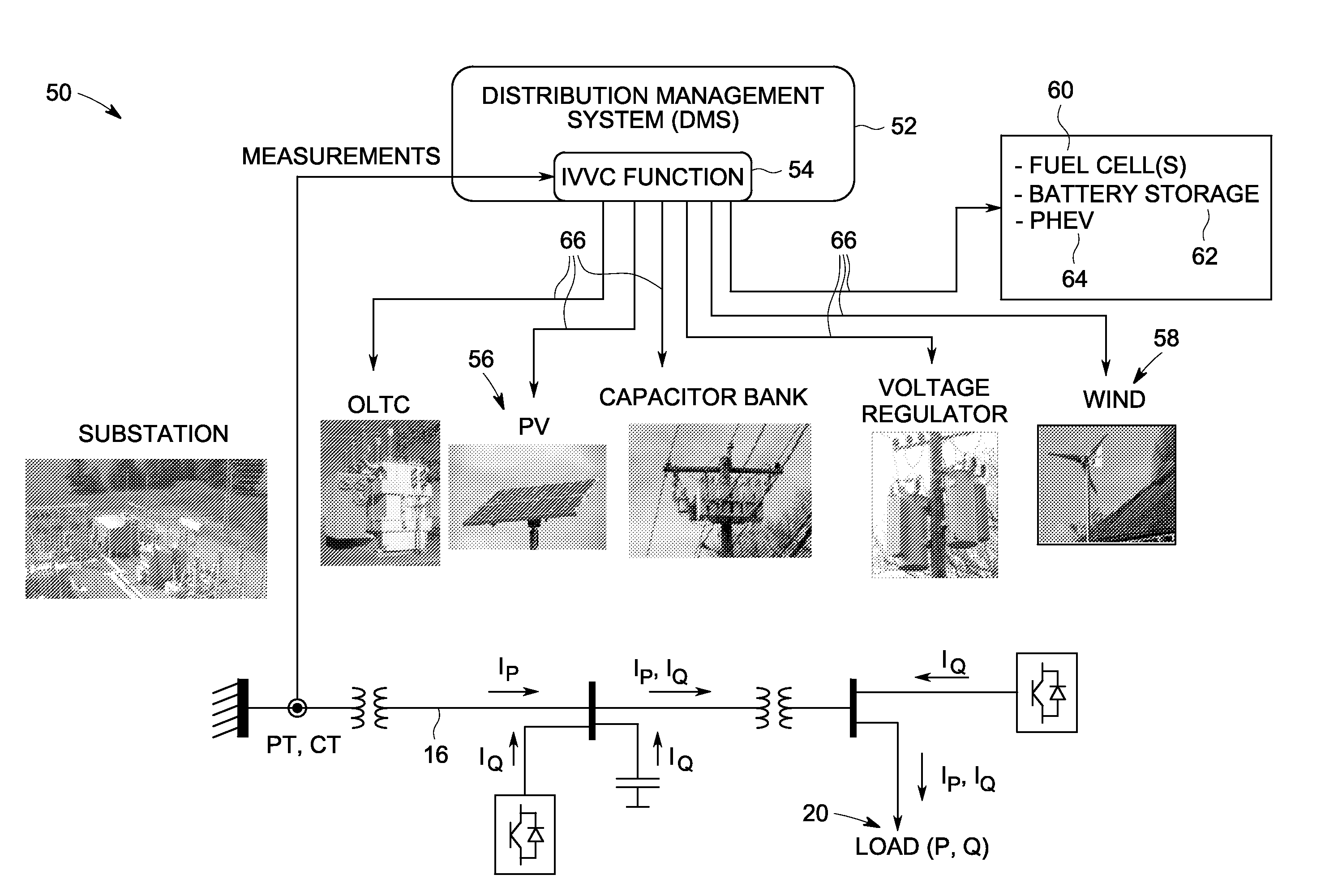
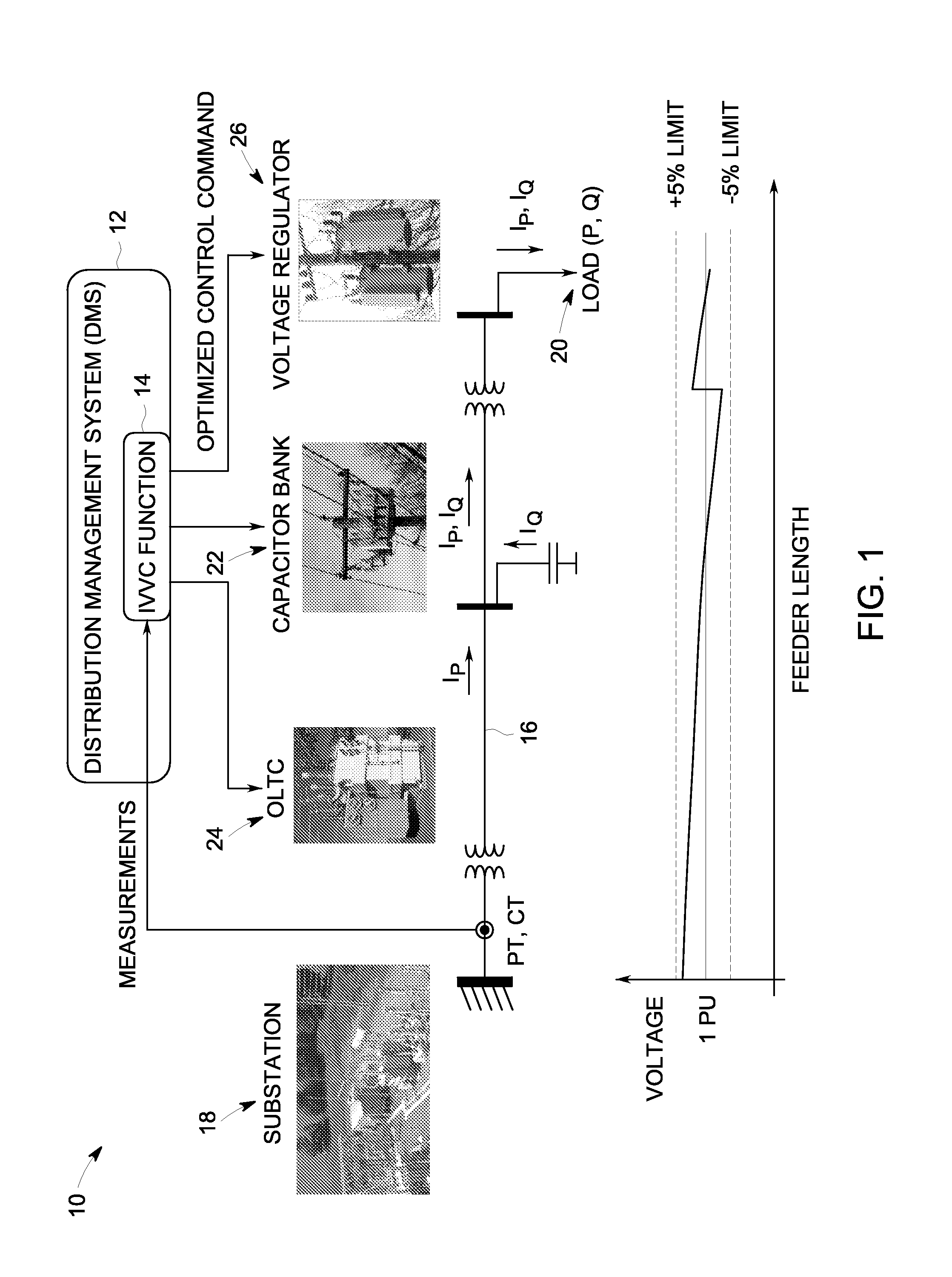
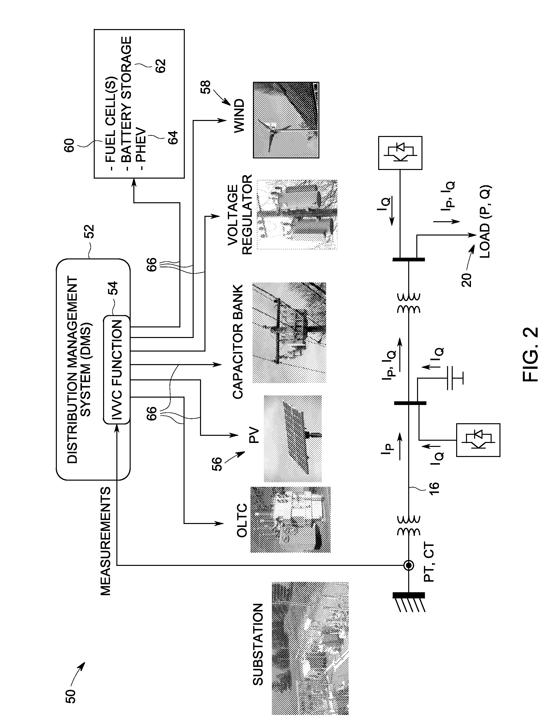
[0024]FIG. 1 illustrates a power distribution system 10 comprising a conventional distribution management system (DMS) 12. The DMS 12 operates in response to an integrated volt / var control (IVVC) system 14 comprising an algorithmic optimization software. Fundamentals of VAR compensation and voltage regulation are first described herein with reference to FIG. 1 to provide a better understanding of the embodiments described herein with reference to FIG. 2.

[0025]When a user load consumes reactive power (Q) as well as real power (P) in a distribution system, current has to flow over a feeder 16 in order to transfer real power and reactive power from a substation 18 to the user end, or load (20) if there is no reactive power compensation in between the substation 18 and the user end or load (20). Although reactive power does not represent real energy consumption (in fact, it is the energy bouncing between reactive and capacitive devices), it does increase the magnitude of that current fl...


PUM


Abstract

A distribution management system (DMS) includes an integrated volt / var controller (IVVC) that is configured to control operation of at least one corresponding renewable energy source or energy storage device power converter in response to IVVC commands generated via algorithmic optimization software integrated within the IVVC. At least one renewable energy source or energy storage device is controlled to operate alone or in coordination with one or more discrete step size reactive power (VAR) compensation devices to generate continuously varying reactive power required by a corresponding power distribution system.

Description

BACKGROUND[0001]The invention relates generally to integrated volt / var control systems, and more particularly to a system and method of integrating renewable power generating technologies with integrated volt / var control systems.[0002]Large inductive loads such as air conditioners, furnaces, dryers, and the like can consume reactive power (VARs) in addition to real power (Watts). Transferring reactive power over transmission lines and distribution feeders involves I2R losses that have to be supplied by utilities. Since residential power meters only measure Watts that are used to determine customer billing requirements, utilities want to minimize the number of VARs consumed. This result is generally achieved by switching in capacitor banks to compensate for VAR losses locally in distribution systems.[0003]Besides capacitor banks to provide VAR compensation, distribution systems are also equipped with voltage regulation devices (e.g., On Load Tap Changer—OLTC, or voltage regulator—VR)...

Claims


Application Information

Patent Timeline
IPC IPC(8): H02J4/00
CPCH02J3/1828Y02E40/30Y02E10/763H02J3/386H02J2300/28H02J3/381Y02E10/76H02J2300/24H02J2300/30H02J3/50Y02E10/56
Inventor O'BRIEN, KATHLEEN ANNREN, WEI
Owner GENERAL ELECTRIC CO
Learn More