Printing apparatus

Active Publication Date: 2012-05-31
CANON KK
View PDF4 Cites 3 Cited by
  • Summary
  • Abstract
  • Description
  • Claims
  • Application Information

AI Technical Summary

Benefits of technology

[0007]The present invention is directed to a printing apparatus in which the possibility that the sheet comes into contact with the printing head, or the quality of the printed image is aggravated has been reduced.

Problems solved by technology

Such corrugation, which is particularly noticeable in a continuous sheet, can also be generated in a cut sheet, which is previously cut in a predetermined length.
Even if the contact with the printing head does not occur, the distance between the printing head and the sheet surface varies in accordance with the corrugation, so that the requisite flying time for the ink discharged from the printing head to impinge upon the sheet varies, making it rather difficult to perform accurate image printing.

Method used


Image

  • Printing apparatus
  • Printing apparatus
  • Printing apparatus

Examples


Embodiment Construction

[0020]Various exemplary embodiments, features, and aspects of the invention will be described in detail below with reference to the drawings.

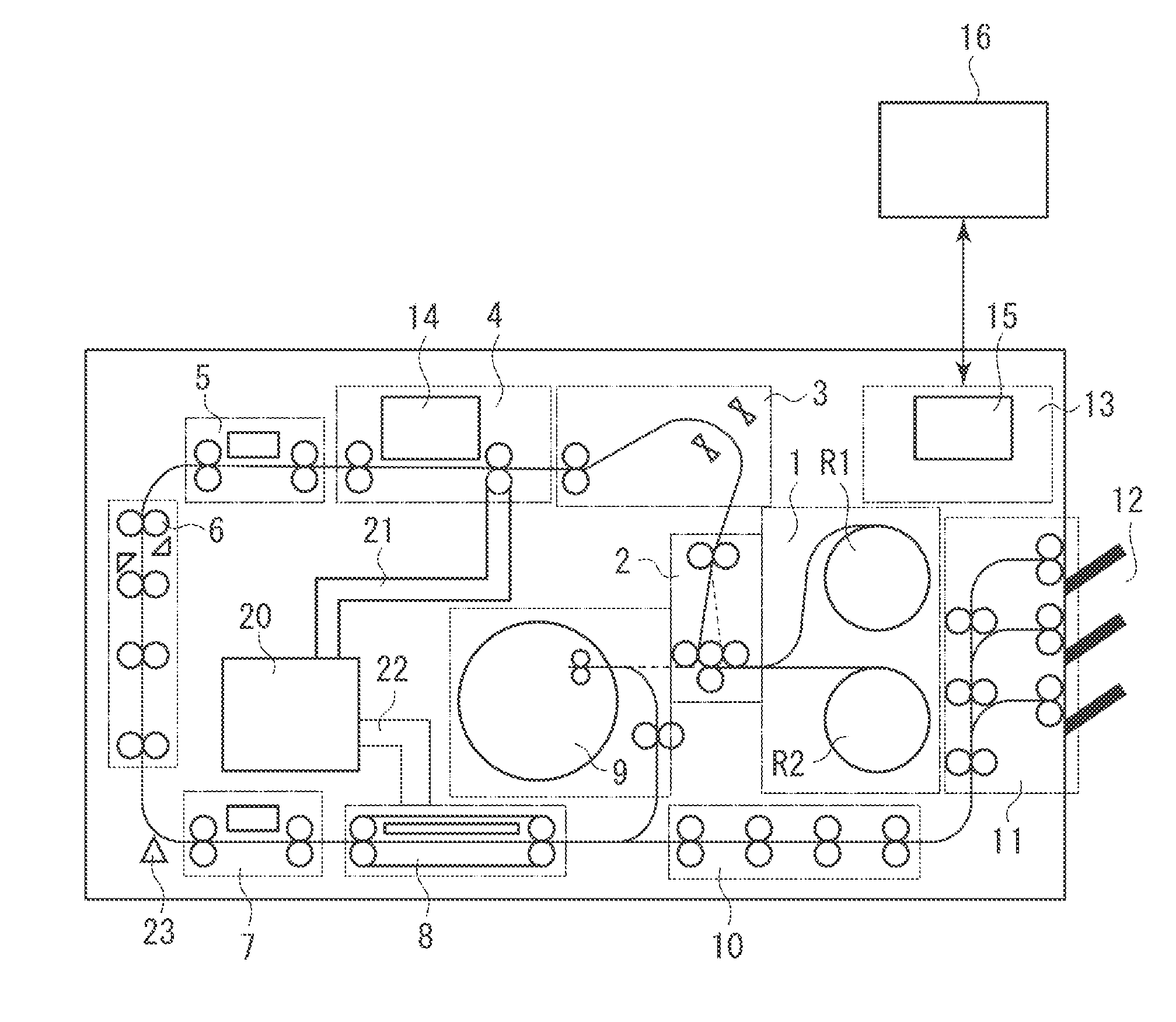
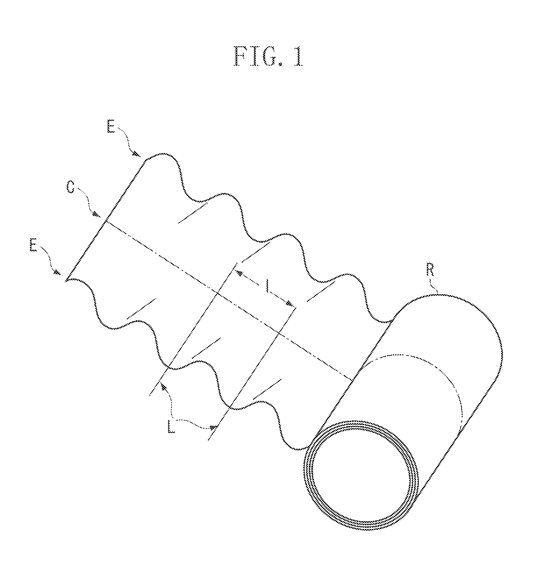
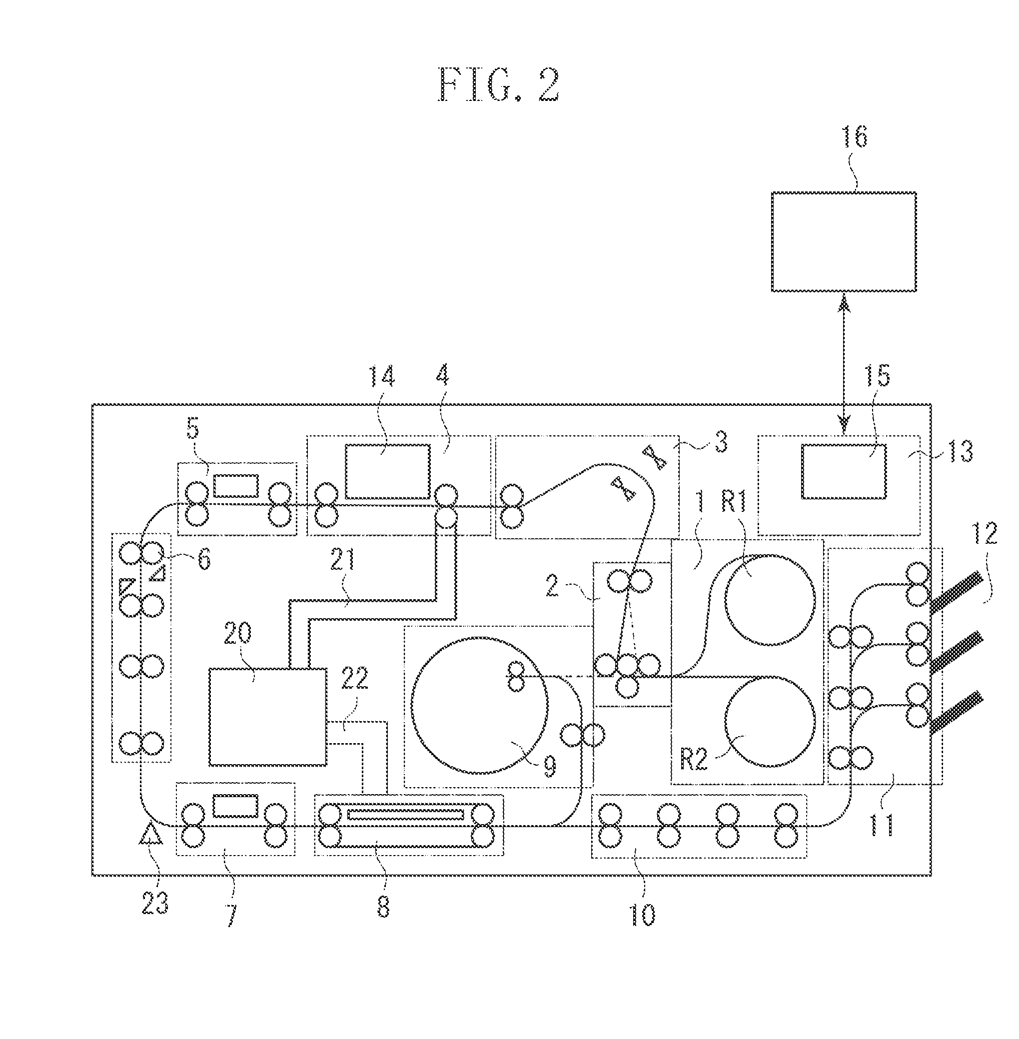
[0021]In the following, an exemplary embodiment of a printing apparatus using an inkjet system will be illustrated. The printing apparatus of this exemplary embodiment is a high speed line printer which uses an elongated continuous sheet (a continuous sheet whose length is larger than the length of a printing unit repeated in the conveyance direction (referred to as one page or a unit image)) and which is applicable to both simplex printing and duplex printing. For example, the printing apparatus is suitable for use in the field where printing is performed in large quantities in a printing laboratory or the like. In the present specification, even if there exist in a mingled state a plurality of small images, characters, and blanks in the region of one print unit (one page), what is contained in that region will be collectively referred to as o...


PUM

PropertyMeasurementUnit
Forceaaaaaaaaaa
Speedaaaaaaaaaa

Abstract

A printing apparatus includes: a upstream roller pair arranged on the upstream side of a printing head with respect to a direction in which a sheet is conveyed; and a downstream roller pair arranged on the downstream side of the printing head with respect to the direction, wherein each of the upstream roller pair and the downstream roller pair includes a first roller and a second roller configured to hold the sheet therebetween. In both of the upstream roller pair and the downstream roller pair, a rotation shaft of the second roller is provided to be situated on the downstream side of a rotation shaft of the first roller with respect to the direction.

Description

BACKGROUND OF THE INVENTION[0001]1. Field of the Invention[0002]The present invention relates to a printing apparatus printing an image on a sheet.[0003]2. Description of the Related Art[0004]There is an inkjet type printing apparatus using a continuous sheet rolled up in the form of a roll. Japanese Patent Application Laid-Open No. 2008-222419 discusses an apparatus in which, on the upstream side of a print unit in which a plurality of printing heads are arranged, there is provided a decurling unit configured to remove curl from a continuous sheet.[0005]At the time of its manufacture, a continuous sheet in the form of a roll is pulled under a fixed tension as it is rolled up on a core. In an ordinary manufacturing method, the pulling force applied at the time of rolling up is larger at the end portions than in the central portion of the sheet in the sheet width direction, so that, in some cases, the entire length of the product sheet is larger at both end portions E than in the cen...

Claims


Application Information

Patent Timeline
IPC IPC(8): B41J2/01B65H5/06
CPCB41J11/0005B41J13/02B65H2801/15B65H2801/09B65H2701/1313B65H2701/1311B65H2513/50B65H2511/514B65H2404/742B65H2404/143B65H2301/517B65H2301/33312B65H85/00B65H20/02B65H5/062B65H5/023B65H2220/01B65H2220/02
Inventor TORIIHARA, SHIGERUNIEDA, KENGOTAKEUCHI, TOSHIKIKAWAGUCHI, KOICHIROSATO, RYOSUKE
Owner CANON KK
Why Eureka
Try Eureka