Liquid crystal display panel and liquid crystal display device

Active Publication Date: 2012-05-31
TRIVALE TECH
View PDF9 Cites 31 Cited by
  • Summary
  • Abstract
  • Description
  • Claims
  • Application Information

AI Technical Summary

Benefits of technology

[0015]The present invention achieves the excellent effect that it can provide a liquid cryst

Problems solved by technology

While described above is the problem in the source line, the similar problem

Method used


Image

  • Liquid crystal display panel and liquid crystal display device
  • Liquid crystal display panel and liquid crystal display device
  • Liquid crystal display panel and liquid crystal display device

Examples


Example

First Exemplary Embodiment

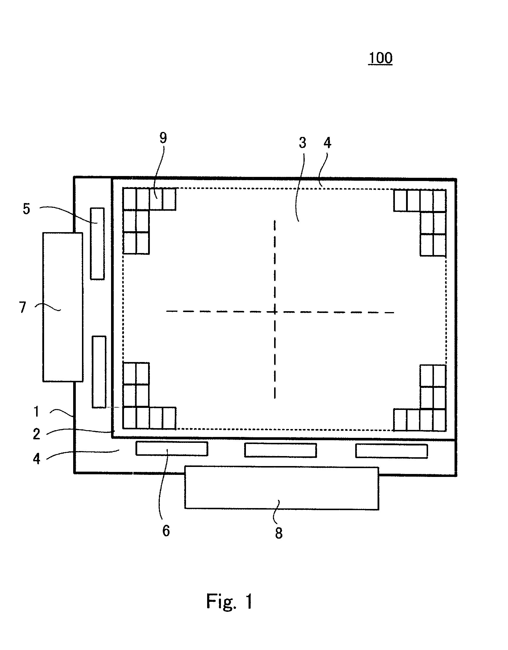
[0036]FIG. 1 is a schematic plane view for describing one example of a liquid crystal display panel mounted on a liquid crystal display device according to a first exemplary embodiment of the present invention. The liquid crystal display device includes a liquid crystal display panel 100 of active matrix type in which an array substrate 1 which is a first substrate is arranged opposite to a color filter substrate 2 which is a second substrate with liquid crystal interposed therebetween. The array substrate 1 includes gate lines, source lines, TFTs, pixel electrodes, a transparent common electrode supplied with a reference potential and the like formed on a transparent substrate made of glass, plastic, or the like. The color filter substrate 2 includes a color filter, a black matrix which is a light-shielding layer and the like formed on a transparent substrate made of glass, plastic, or the like.

[0037]The liquid crystal display panel 100 includes a display ...

Example

Second Exemplary Embodiment

[0082]Next, one example of a liquid crystal display device having a structure different from that of the first exemplary embodiment will be described. In the following description, the same element members as those in the first exemplary embodiment are denoted by the same reference symbols, and its description will be omitted as appropriate.

[0083]Described in the second exemplary embodiment is one example of the liquid crystal display device that aims to improve contrast from an oblique direction in addition to contrast from a frontal direction.

[0084]FIG. 11A is an explanatory view of absorption axes of a lower-side polarizing plate 53 and an upper-side polarizing plate 54 seen from a frontal direction, and FIG. 11B is an explanatory view of absorption axes of the lower-side polarizing plate 53 and the upper-side polarizing plate 54 seen from an oblique direction. When the liquid crystal display panel is seen from the frontal direction, the angle of the ab...

Example

Third Exemplary Embodiment

[0093]A basic structure of a liquid crystal display device according to a third exemplary embodiment is similar to that of the first exemplary embodiment except the following point. The third exemplary embodiment differs from the first exemplary embodiment in that source lines and a transparent common electrode are made in a linear shape.

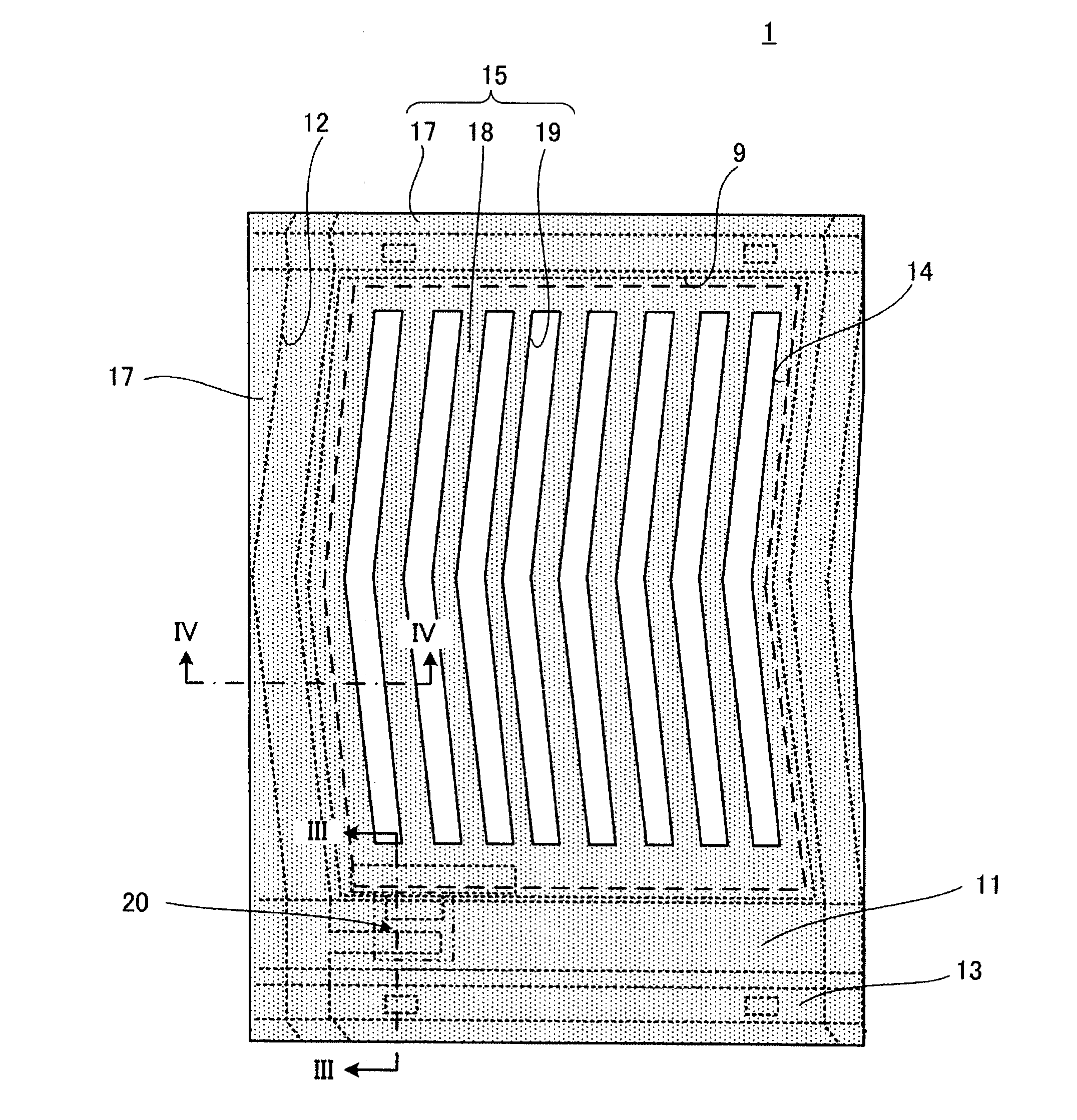
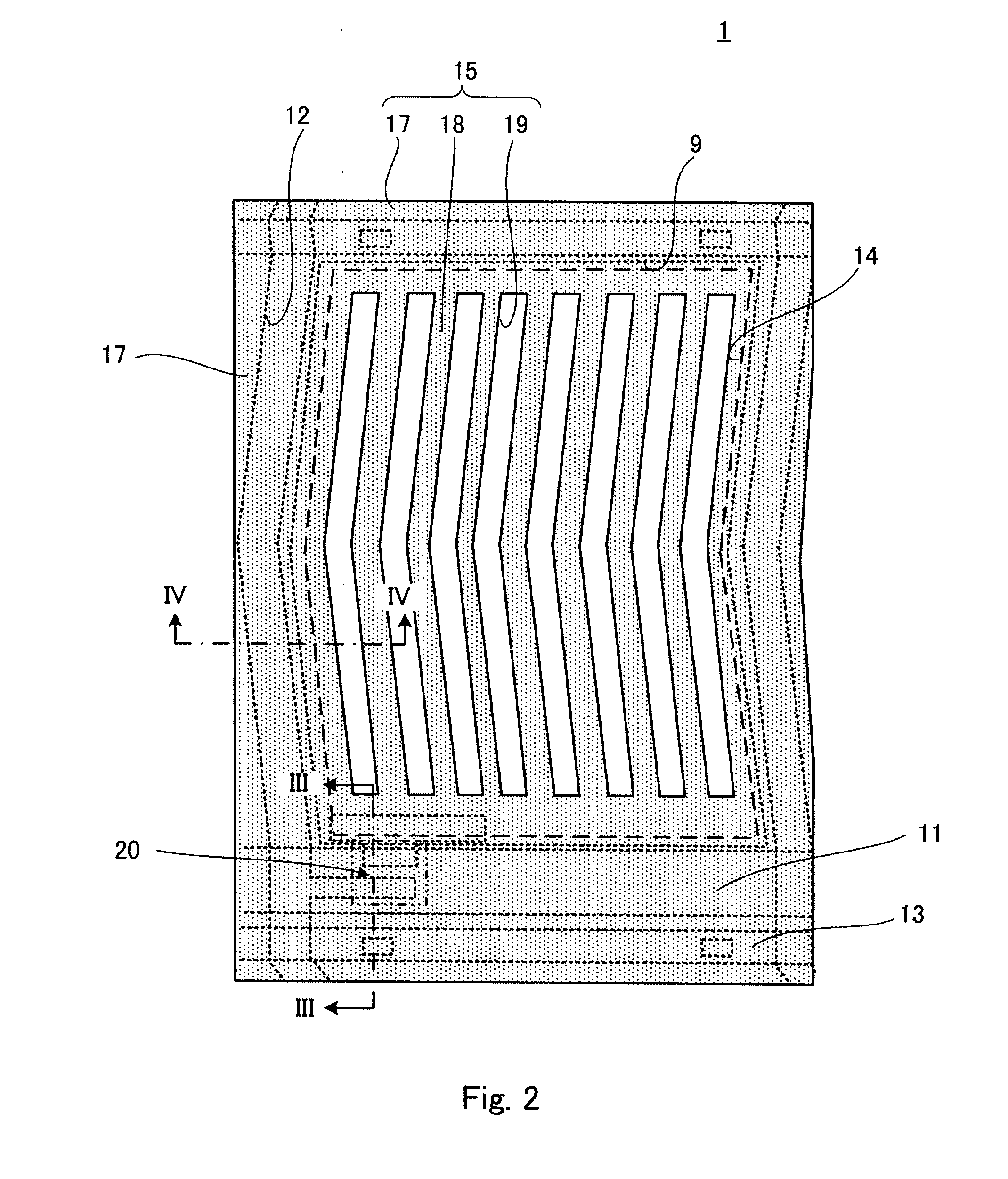
[0094]FIG. 16 shows a schematic plane view of a main part of an array substrate 1b of the liquid crystal display device according to the third exemplary embodiment. The array substrate 1b includes a source line 12b that is formed in a linear shape. Further, as is similar to the source line 12b, a transparent common electrode 15b includes branch-like electrode parts 18b and gap parts 19b which are made in a linear shape.

[0095]It is considered that the reason why the light leakage occurs due to the alignment defect of the liquid crystal 50 beside the source line 12b is that, since the step of the source line 12b is typically ...


PUM


Abstract

A liquid crystal display panel includes switching elements, transparent pixel electrodes, and a transparent common electrode having a predetermined area overlapped with an upper layer of the transparent pixel electrode through an insulating film and driving liquid crystal with the transparent pixel electrode. In plane view, a shading layer covers at least one part of a conductive pattern where a light leakage occurs in front view by an alignment defect of the liquid crystal near a non-permeable conductive pattern disposed in the display region at the time of black display, and has eaves more protruding than the conductive pattern. The transparent common electrode is provided to overlap with the conductive pattern arranged to overlap with the light-shielding layer having the eaves in a side of the liquid crystal and to protrude compared with the light-shielding layer having the eaves in a planar view.

Description

INCORPORATION BY REFERENCE[0001]This application is based upon and claims the benefit of priority from Japanese patent application No. 2010-261948, filed on Nov. 25, 2010, the disclosure of which is incorporated herein in its entirety by reference.BACKGROUND OF THE INVENTION[0002]1. Field of the Invention[0003]The present invention relates to a liquid crystal display panel and a liquid crystal display device. More specifically, the present invention relates to a liquid crystal display panel and a liquid crystal display device of fringe field switching (FFS) type.[0004]2. Description of Related Art[0005]In recent years, in substitution for a conventional cathode-ray tube, new display devices having a thin flat-type display panel using principles of liquid crystal, electroluminescence or the like have been frequently used. A liquid crystal display device which represents these new display devices has characteristics in that it can be driven with a low power voltage, in addition to its...

Claims


Application Information

Patent Timeline
IPC IPC(8): G02F1/1339
CPCG02F1/133512G02F2001/134318G02F1/136286G02F1/133528G02F1/13363G02F1/134309G02F1/1368G02F1/134318G02F1/134372G02F1/133345G02F1/1339G02F1/13439G02F2201/121G02F2201/123G02F2413/12
Inventor YONEMURA, KOJI
Owner TRIVALE TECH
Why Eureka
Try Eureka