Holey fiber

Active Publication Date: 2012-05-31
FURUKAWA ELECTRIC CO LTD
View PDF6 Cites 5 Cited by
  • Summary
  • Abstract
  • Description
  • Claims
  • Application Information

AI Technical Summary

Benefits of technology

[0013]It is an object of the present invention to at least

Problems solved by technology

That is, in the optical transmission, for instance, especially in a case of conducting a long-distance terrestrial transmission or an undersea transmission, there is a problem in that a nonlinear optical phenomenon of optical fiber be

Method used


Image

  • Holey fiber
  • Holey fiber
  • Holey fiber

Examples


Embodiment Construction

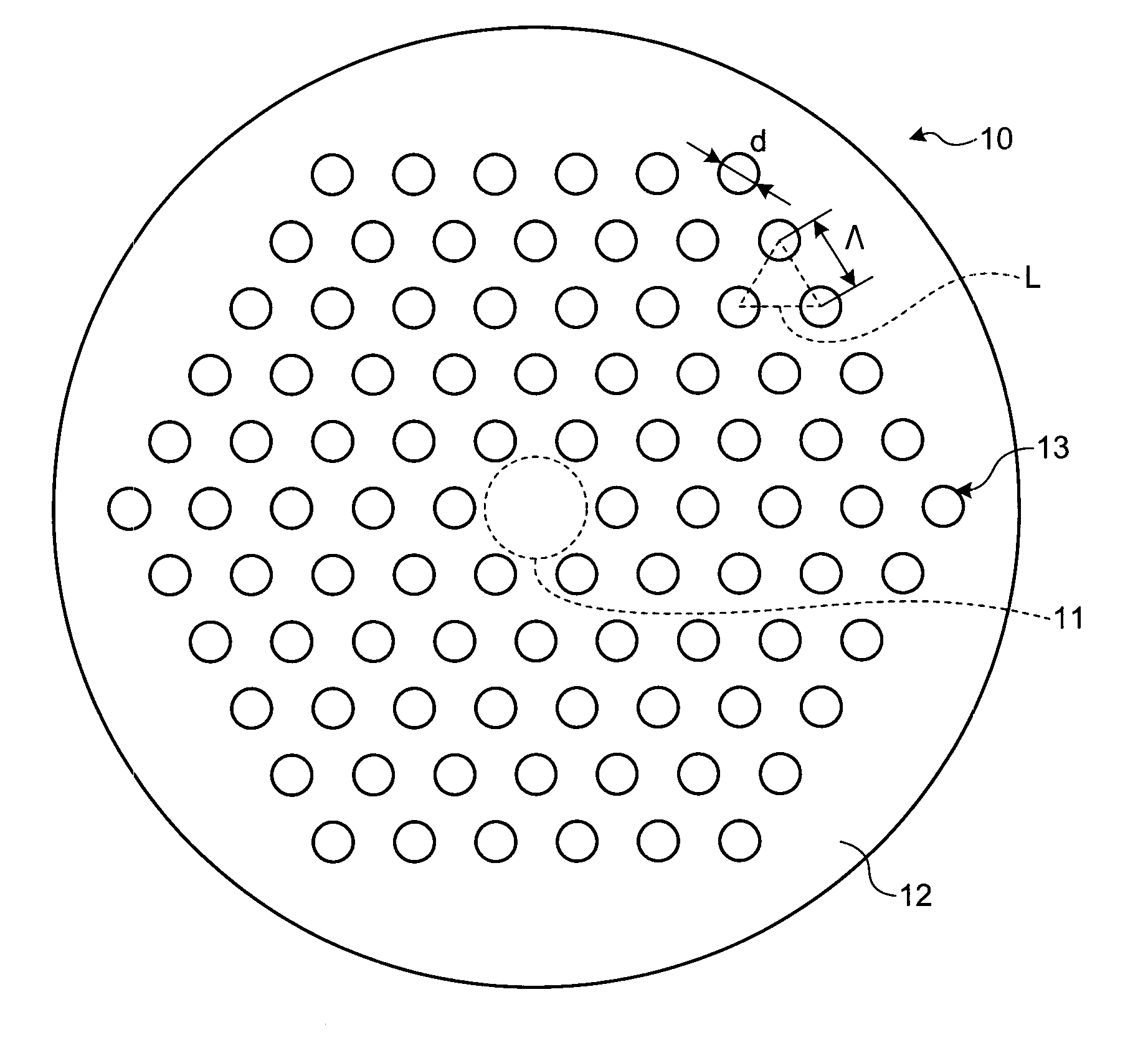
[0029]In recent years, there has been a strong demand for a holey fiber that can realize lower optical nonlinearity and more suppressed bending loss than a conventional fiber while realizing a single-mode operation, for application to optical transmission.

[0030]In the following, an embodiment of a holey fiber suitable to be used in optical transmission will be described in detail with reference to the accompanying drawings. The holey fiber according to the embodiment can realize low optical nonlinearity and suppressed bending loss while realizing a single-mode operation. The present invention is not limited to this preferred embodiment. The holey fiber is described as “HF” herein, accordingly. In this description, a cut-off wavelength (λc) indicates a fiber cut-off wavelength as defined in ITU-T (International Telecommunication Union) G.650.1. The terms not particularly defined in the present specification follow the definitions and measuring methods according to the ITU-T G.650.1.

[...


PUM


Abstract

A holey fiber includes a core portion located at a center of the holey fiber, and a cladding portion located around the core portion, the cladding portion having holes formed in layers around the core portion. The holes are arranged so as to form a triangular lattice while d/Λ is within a range of 0.33 to 0.43, Λ is within a range of 10.5 micrometers to 15 micrometers when a hole diameter is d in micrometer and a lattice constant of the triangular lattice is Λ in micrometer, and in a wavelength of 1550 nanometer, an effective core-area is equal to or greater than 130 μm2, a bending loss in a case of bending the holey fiber at a bend diameter of 20 millimeters is equal to or less than 200 dB/m, and the holey fiber demonstrates a single-mode operation.

Description

CROSS-REFERENCE TO RELATED APPLICATIONS[0001]This application is a continuation of PCT International Application No. PCT / JP2011 / 056150 filed on Mar. 16, 2011 which claims the benefit of priority from the prior Japanese Patent Applications No. 2010-059959, filed on Mar. 16, 2010; the entire contents of which are incorporated herein by reference.BACKGROUND OF THE INVENTION[0002]1. Field of the Disclosure[0003]The present invention relates to a holey fiber.[0004]2. Description of the Related Art[0005]A holey fiber (HF) or a photonic crystal fiber is a new type of optical fiber which realizes optical transmission using the principle of total reflection while reducing an average refractive index by having holes arranged regularly in a cladding layer. By using holes for controlling refractive index of optical fiber, the holey fiber can realize unique characteristics which have not been able to be realized by a conventional optical fiber, such as an endlessly single mode characteristic (ES...

Claims


Application Information

Patent Timeline
IPC IPC(8): G02B6/02
CPCG02B6/02347G02B6/02228
Inventor TSUCHIDA, YUKIHIROMUKASA, KAZUNORI
Owner FURUKAWA ELECTRIC CO LTD
Why Eureka
Try Eureka