
Fan speed control system and fan speed reading method thereof

a control system and fan technology, applied in the server field, can solve the problems of ineffective method of pre-reading the fan rotation speed, inability to adjust the fan rotation speed in real time, and inability to accurately read the fan rotation speed value, so as to improve the overall transmission efficiency of the system

Inactive Publication Date: 2012-05-31
INVENTEC CORP
View PDF26 Cites 22 Cited by
  • Summary
  • Abstract
  • Description
  • Claims
  • Application Information

AI Technical Summary

Benefits of technology

[0007]Accordingly, an aspect of the present invention provides a fan speed control system, which can avoid occupying a bus unnecessarily so as to improve the overall transmission efficiency of the system and meanwhile can avoid the occurrence of the case that the bus is contested by multiple modules.
[0009]Another aspect of the present invention provides a fan speed control system, which can avoid occupying a bus unnecessarily so as to improve the overall transmission efficiency of the system and meanwhile can avoid the occurrence of the case that the bus is contested by multiple modules.

Problems solved by technology

However, the method of pre-reading the fan rotation speed is not very effective.
Particularly, when the fan rotation speed is read for many times, the case that the bus is inappropriately occupied or the case that the bus is contested may occur, which results in that a fan rotation speed value cannot be read correctly.
Thus, the fan rotation speed cannot be adjusted in real time and the fan heat dissipation performance is reduced.

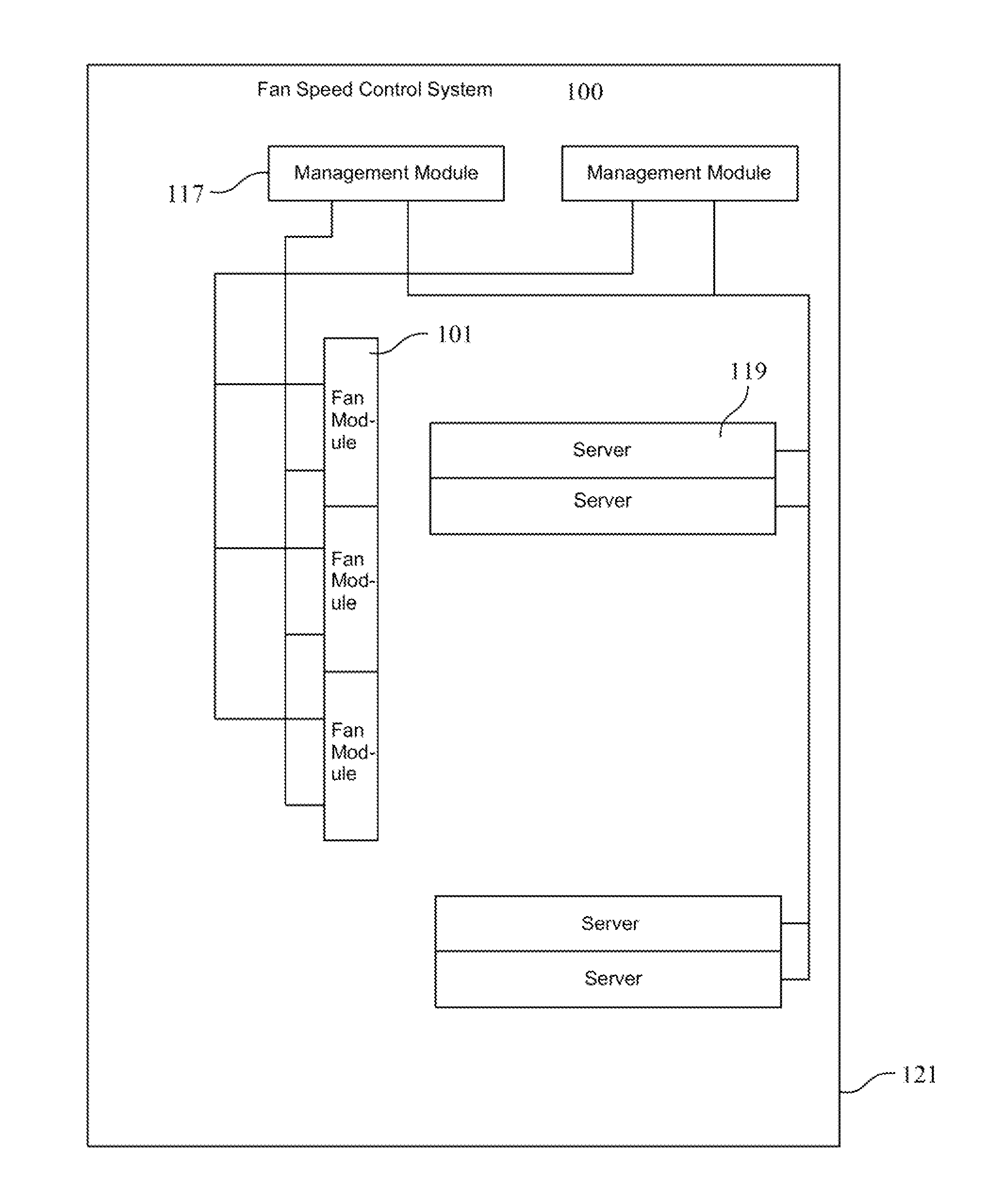
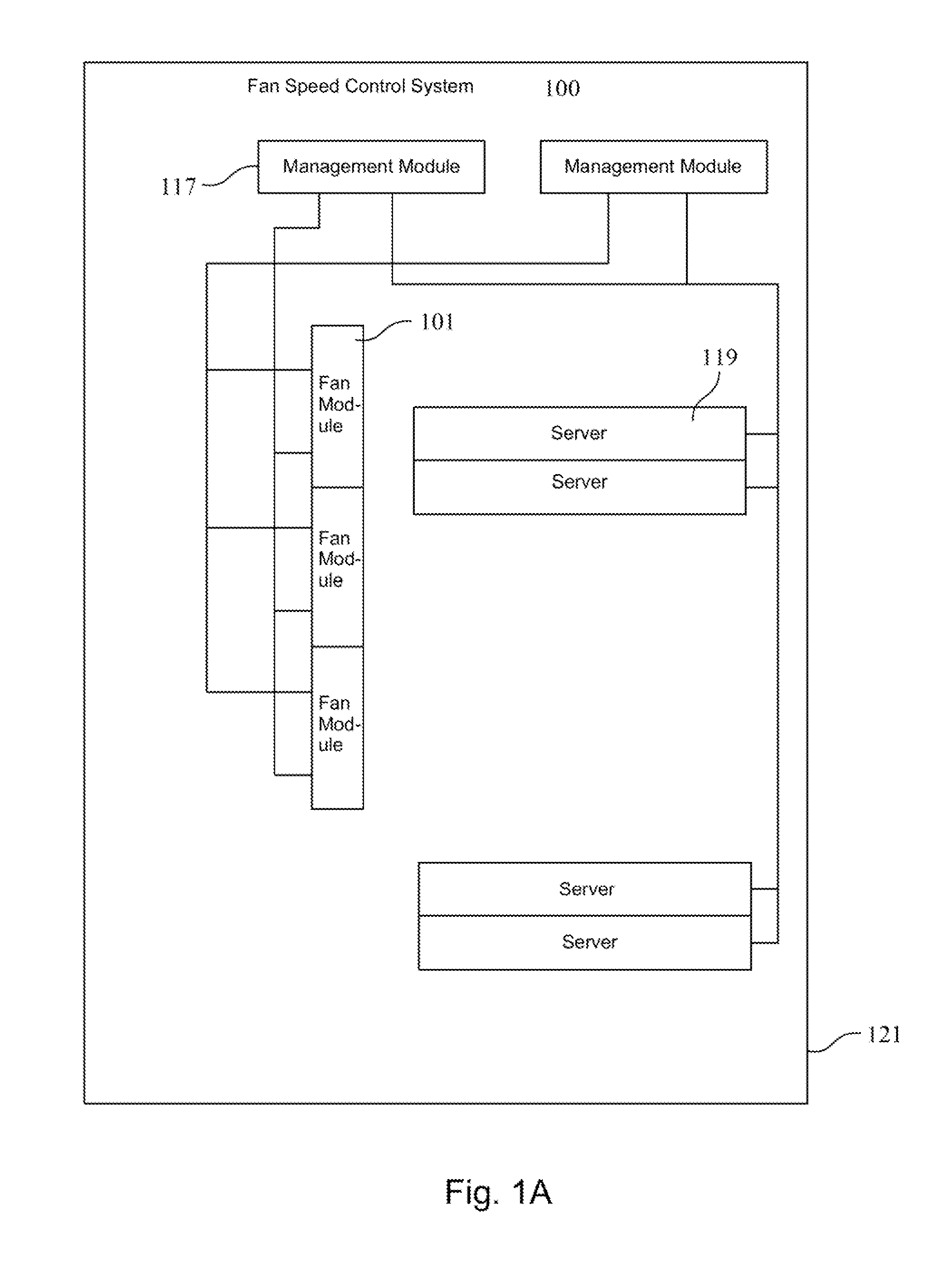
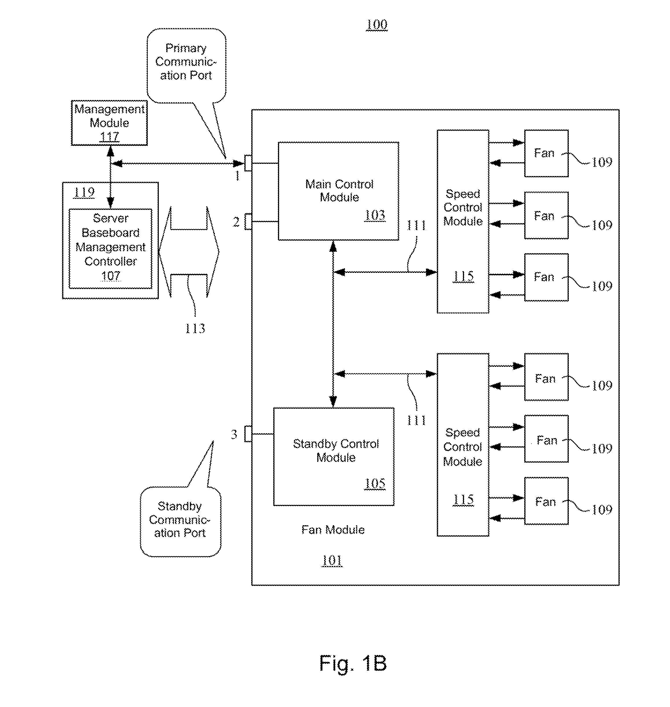
Method used


Image

  • Fan speed control system and fan speed reading method thereof
  • Fan speed control system and fan speed reading method thereof
  • Fan speed control system and fan speed reading method thereof

Examples


Embodiment Construction

[0018]After a main control module completes the initialization of a speed control module, the main control module keeps waiting for a command given by a server baseboard management controller. Only when receiving a complete and correct fan rotation speed reading command, the main control module accesses a fan rotation speed stored in the speed control module. The main control module does not access the fan rotation speed stored in the speed control module at any other time. Another standby control module does not access the speed control module when the main control module operates normally. Therefore, it can be avoided that multiple modules access the speed control module at the same time and thus contest the bus.

[0019]Referring to FIGS. 1A and 1B at the same time, FIGS. 1A and 1B are respectively a schematic structural view of a fan speed control system according to an embodiment of the present invention and a block diagram of the fan speed control system. The fan speed control sy...


PUM


Abstract

A fan speed control system includes a rack and a plurality of servers disposed on the rack. The fan speed control system further includes the management module and the fan module. The management module is coupled to the servers, and the fan module is coupled to the management module for dissipating the heat from the servers. The fan module contains the fan, the speed control module, and the main control module. The speed control module is coupled to the fans. The main control module has a primary communication port. The main module which enters the interrupt sequence receives the control signals sent from the management module through the primary communication port when any one of the main modules enters the interrupt sequence. The control signal is delivered to the speed control module for reading the fan speed.

Description

RELATED APPLICATIONS[0001]This application claims priority to China Application Serial Number 201010575249.7, filed Nov. 30, 2010, which is herein incorporated by reference.BACKGROUND[0002]1. Field of Invention[0003]The present invention relates to a server, and more particularly to a server with a fan.[0004]2. Description of Related Art[0005]In general, multiple motherboards are arranged in a rack of a server or a computer system, and elements (e.g. a central processing unit (CPU), etc.) arranged on the motherboards produce a high temperature during working. Thus, in order to avoid that the work performance of the elements is affected by the high temperature or the elements are burned out due to the high temperature, heat dissipation measures should be provided for the elements. That is, corresponding fans should be arranged near the motherboards, so as to decrease the high temperature produced by the elements on the motherboards. The fans can be managed and controlled by a fan con...

Claims


Application Information

Patent Timeline
IPC IPC(8): G05D23/19
CPCF04D27/004F04D25/166Y02B30/70
Inventor LIU, GUI-MING
Owner INVENTEC CORP
Learn More