
Network device and network connecting method for building up network connection via high definition multimedia interface

a network connection and multimedia interface technology, applied in the direction of signal allocation, transmission path sub-channel allocation, instruments, etc., can solve the problem of further affecting the quality of the receiving signal, the receiving end of the network device is unable to distinguish whether the received signal is from the other network, and the connection failure, so as to avoid the problem of echo interference caused by the transmission signal

Active Publication Date: 2012-05-31
REALTEK SEMICON CORP
View PDF10 Cites 14 Cited by
  • Summary
  • Abstract
  • Description
  • Claims
  • Application Information

AI Technical Summary

Benefits of technology

[0007]It is therefore one of the objectives of the disclosure to provide a network device and a network connecting method for building up network connections via HDMI, such that the problems of echo interference caused by the transmission signal can be solved by comparing a time distance between a first seed of the transmission signal and a second seed of the receiving signal with a threshold during the initial network connection.
[0010]Therefore, by comparing a time distance between the first seed and the second seed in the disclosure, the receiving signal received by the receiving unit of the network device can be determined to check whether it is the signal from another network device or it is the echo signal resulted form the transmission signal. As a result, the problems of echo interference caused by the transmission signal can be avoided. Furthermore, by controlling the transmitting unit to stop sending the transmission signal for a predetermined time duration, a power-saving effect can be achieved.

Problems solved by technology

For this reason, the transmission signal is likely to bounce back and cause echo, which may further affects the quality of the receiving signal.
Under this condition, the receiving end of the network device is unable to distinguish whether the received signal is from the other network device or the echo signal caused by the transmission signal.
For this reason, the echo signal caused by the transmission signal may be mistaken as the signal from the other network device, which may fail in building up a network connection.
During the initial network connection, the echo signal caused by the transmission signal will be mistaken as the signal from the other network device, which may result in not only connection failure but also unnecessary power consumption and waste of power.

Method used


Image

  • Network device and network connecting method for building up network connection via high definition multimedia interface
  • Network device and network connecting method for building up network connection via high definition multimedia interface
  • Network device and network connecting method for building up network connection via high definition multimedia interface

Examples


first embodiment

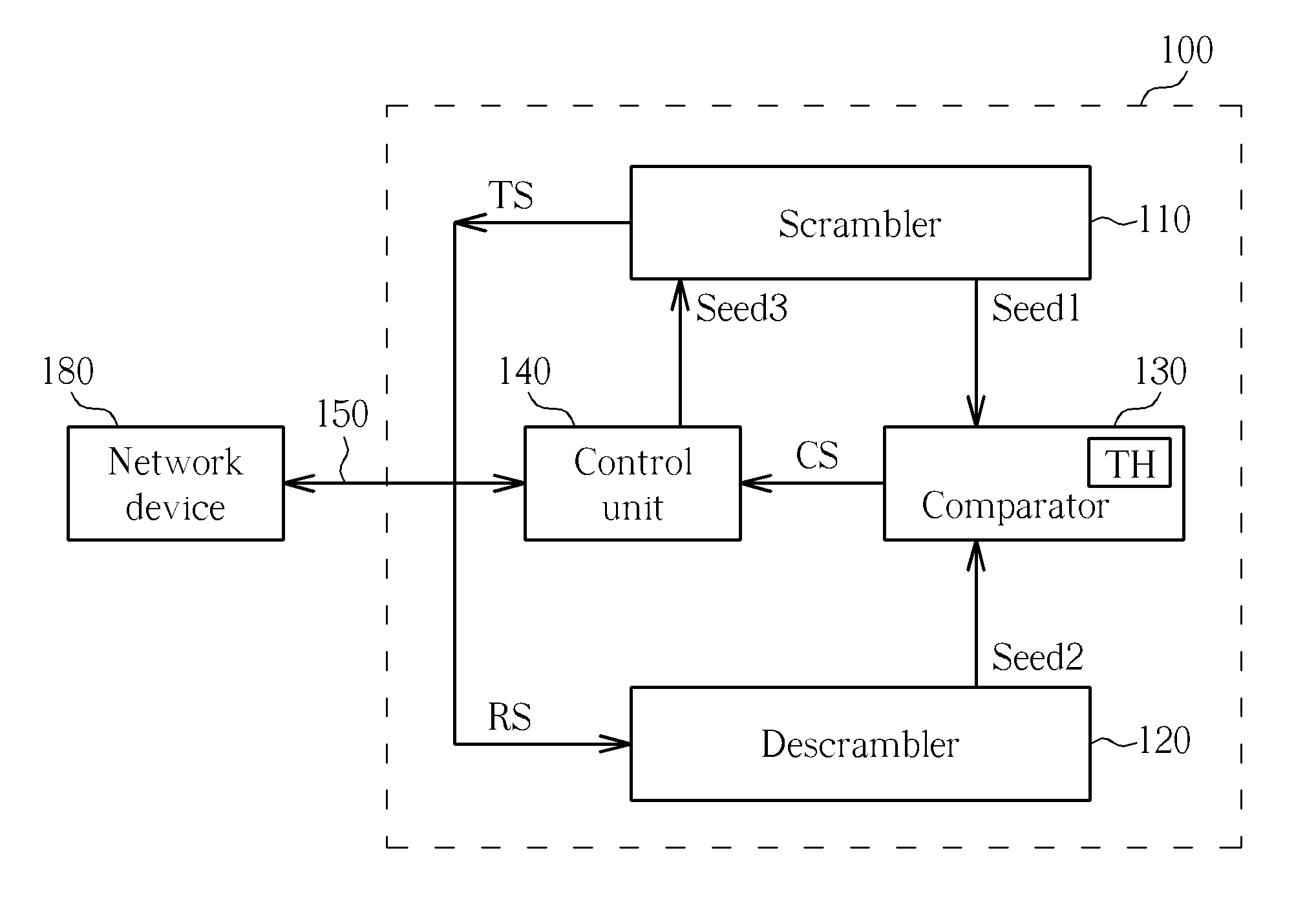
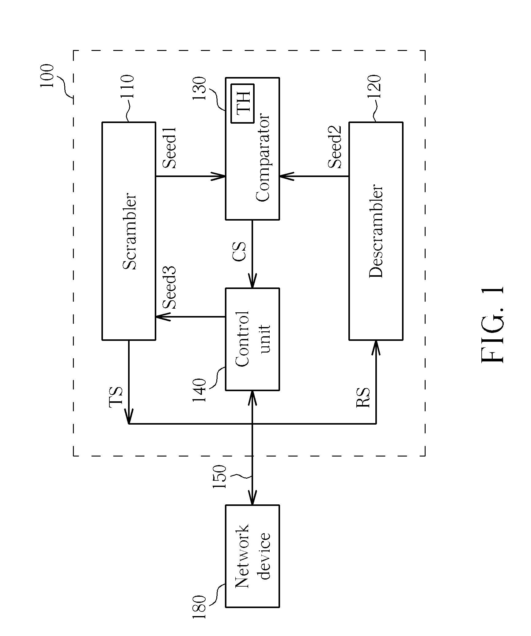
[0025]Please refer to FIG. 1. FIG. 1 is a block diagram illustrating a network device 100 for building up a network connection via a high-definition multimedia interface (HDMI) 150 according to a As shown in FIG. 1, the network device 100 may include, but is not limited to, a scrambler 110, a descrambler 120, a comparator 130 and a control unit 140. During the initial network connection, the scrambler 110 is arranged for generating a transmission signal TS according to a first seed SEED1. Please note that, in this embodiment, the transmission signal TS can use an idle sequence as an example, but the disclosure is not limited to this only. The descrambler 120 is coupled to the scrambler 110, and is arranged for decoding a receiving signal RS to generate a second seed SEED2. In addition, the comparator 130 is coupled to the scrambler 110 and the descrambler 120, and is arranged for generating a comparing result CS according to the first seed SEED1 and the second seed SEED2. The contr...

second embodiment

[0028]Please refer to FIG. 3B. FIG. 3B is a diagram illustrating the comparator for generating the comparing result according to a As shown in FIG. 3B, in other embodiments, the reference value determining unit 332 may use a middle position (such as, 1024) of the pseudo-noise sequence as the seed position reference value. At this time, the computing unit 334 then determine the comparing result CS by calculating a sum of a first time distance T1, between the first seed SEED1 and the middle position, and a second time distance T2, between the second seed SEED2 and the middle position. For example, if the first time distance T1 between the first seed SEED1 and the middle position is equal to 10 and the second time distance T2 between the second seed SEED2 and the middle position is equal to 15, the comparing result CS is determined to be 25 (i.e., 10+15=25).

third embodiment

[0029]Please refer to FIG. 3C. FIG. 3C is a diagram illustrating the comparator for generating the comparing result according to a As shown in FIG. 3C, the reference value determining unit 332 may divide the pseudo-noise sequence into four equal portions, and may use their corresponding positions (such as, Q1, Q2, Q3, and Q4) as four seed position reference values. If the first time distance between the first seed SEED1 and the seed position reference value Q2 counted by the computing unit 340 is equal to 10 counted, and the second time distance between the second seed SEED2 and the seed position reference value Q4 counted by the computing unit 340 is equal to 15, the comparing result CS is determined to be 1049(i.e., 10+15+1024=1049).

[0030]As can be known from above, the number of the seed position reference values set by the reference value determining unit 332 gets large, the time distance between the first seed and the seed position reference value can be calculated by the comp...


PUM


Abstract

A network device for building up a network connection via a high-definition multimedia interface, includes a scrambler, a descrambler, a comparator and a control unit. The scrambler is utilized for generating a transmission signal according to a first seed. The descrambler is for decoding a receiving signal to generate a second seed. The comparator is for generating a comparing result according to the first seed and the second seed. The control unit is for controlling the network connection according to the comparing result.

Description

BACKGROUND[0001]1. Technical Field[0002]The disclosure relates to a network device and a network connecting method for building up network connections via a high-definition multimedia interface (HDMI).[0003]2. Description of the Related Art[0004]In the high-definition multimedia interface (HDMI) standard version 1.4, a transmission signal and a receiving signal of a network device are transmitted on a single pair of transmission line. For this reason, the transmission signal is likely to bounce back and cause echo, which may further affects the quality of the receiving signal. Especially, when both the network device and another network device send out the same signal (for example, an idle sequence) at the same time, the signal from another network device will be the same as the echo signal caused by the transmission signal of the network device. Under this condition, the receiving end of the network device is unable to distinguish whether the received signal is from the other netwo...

Claims


Application Information

Patent Timeline
Patent Type & Authority Applications(United States)
IPC IPC(8): G06F11/07
CPCH04L5/001G06F21/606H04L5/0057H04L5/0053
Inventor HUANG, LIANG-WEIKUO, SHIEH-HSINGLIU, CHUN-HUNGCHENG, KAI-WEN
Owner REALTEK SEMICON CORP
Learn More