Turbocharging arrangement and method for operating an internal combustion engine

a technology of internal combustion engine and throttle arrangement, which is applied in the direction of combustion engine, engine components, machines/engines, etc., can solve the problems of slow increase of engine speed and load when requested, low available engine torque, and limited load range of turbochargers, so as to increase load or engine speed, the effect of fast response of the turbocharger

Inactive Publication Date: 2012-06-07
WARTSILA FINLAND OY
View PDF13 Cites 4 Cited by
  • Summary
  • Abstract
  • Description
  • Claims
  • Application Information

AI Technical Summary

Benefits of technology

[0009]The use of an electric motor for assisting the turbocharger enables a fast response of the turbocharger to increased load or engine speed. The engine speed and power output can be increased rapidly and air to fuel ratio can be kept at the optimum level avoiding high smoke emissions during acceleration. Because of infinite adjusting of the torque, optimal charge pressure can be achieved at any operating point of the engine. The engine can be operated at constant speed without a need for a frequency controller. The electric motor can also be used as a generator for reducing the speed of the turbocharger. Energy of the exhaust gases can be utilized optimally and turbocharger waste gates may be redundant.
[0010]According to an embodiment of the invention, the coupling means is an adjustable magnetic coupler. A magnetic coupler is advantageous as the coupling means since there is no mechanical connection between the driving and the driven members of the magnetic coupler. This makes the magnetic couplers reliable and almost maintenance-free.
[0014]By adjusting the torque transmitted by the coupling means between the electric motor and the turbocharger, optimal charge air pressure and quick response to load increase together with minimized smoke emissions can be achieved. Because the torque is adjusted by the adjustable coupling means, there is no need for changing the speed of the electric motor.
[0017]By measuring the actual charge pressure and comparing it to the desired pressure level, accurate control of the turbocharger can be achieved.
[0019]The three different operating modes enable effective use of the turbocharger. When the electric motor is used for assisting the turbocharger, quick load response of the engine can be achieved. By disconnecting the electric motor from the turbocharger, the rotating inertia of the turbocharger can be minimized. By using the electric motor as a generator, the speed of the turbocharger can be reduced by converting the energy of the exhaust gases into electricity.

Problems solved by technology

A disadvantage of turbochargers driven by the exhaust gases is that turbochargers work efficiently only within a limited load range.
Due to this inefficiency, the available engine torque is low at low loads, which leads to slow increase of the engine speed and load when requested.
The response of a turbocharger to a load increase is also delayed since the engine needs to produce more exhaust gases before the turbocharger speed starts to increase.
This results in a reduced air to fuel ratio (lambda) during accelerations and load increases, which may lead to higher smoke emissions.
The slow response of the turbocharger is a problem particularly in applications where an accurate lambda control and quick load response is required.
A disadvantage of compressed air is that it increases the load on the wings on the compressor wheel, and can thus only be used for short periods of time when a quick power increase is needed.
The solutions with electric motors tend to be complicated since a frequency controller is needed for having the possibility to give an electric boost at any load.
A disadvantage of the turbocharger of U.S. Pat. No. 6,305,169 B1 is that the torque transmitted by the eddy current coupling cannot be adjusted but depends on the slip between the drive member and the driven member of the coupling.
Another disadvantage of the turbocharger is that the electric motor cannot be used for braking the turbocharger.

Method used


Image

  • Turbocharging arrangement and method for operating an internal combustion engine
  • Turbocharging arrangement and method for operating an internal combustion engine

Examples


Embodiment Construction

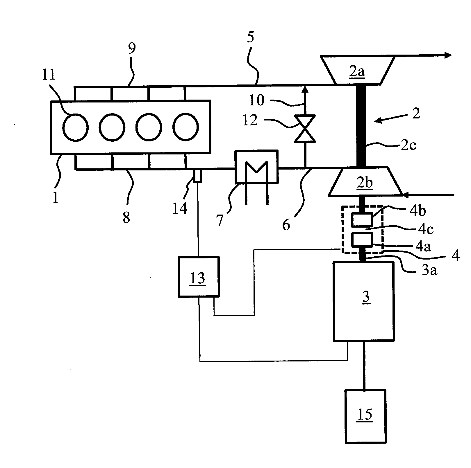
[0022]The invention is now described in more detail with reference to the accompanying drawing. The FIGURE shows a turbocharging arrangement for an internal combustion engine 1 according to an embodiment of the present invention. The arrangement comprises a turbocharger 2 comprising a turbine 2a and a compressor 2b. The turbine 2a and the compressor 2b are connected to each other in a rotationally fixed manner via a shaft 2c.

[0023]The turbine 2a of the turbocharger 2 is connected with an exhaust manifold 9 and exhaust pipe 5 to the cylinders 11 of the engine 1. Via the exhaust manifold 9 and the exhaust pipe 5 the exhaust gases from the engine 1 are guided into the turbine 2a for rotating the turbocharger 2. An intake duct 6 and an intake manifold 8 connect the compressor 2b of the turbocharger 2 to the cylinders 11 of the engine 1. The compressor 2b pressurizes the intake air introduced into the engine 1. A charge air cooler 7 is arranged between the intake duct 6 and the intake m...


PUM


Abstract

A turbocharging arrangement for an internal combustion engine, the arrangement having a turbocharger with a turbine and a compressor connected to a common shaft in a rotationally fixed manner, an electric motor, and coupling means for coupling the electric motor to the shaft of the turbocharger. The coupling means is arranged to steplessly adjust the torque transmitted between the electric motor and the turbocharger. A method for operating a turbocharged internal combustion engine is also provided.

Description

TECHNICAL FIELD OF THE INVENTION[0001]The present invention relates to a turbocharging arrangement for an internal combustion engine, as defined in the preamble of claim 1. The invention also concerns a method for operating a turbocharged internal combustion engine in accordance with the preamble of claim 5.BACKGROUND OF THE INVENTION[0002]Modern internal combustion engines are often equipped with turbochargers to increase the power output, as well as the efficiency of the engine. A disadvantage of turbochargers driven by the exhaust gases is that turbochargers work efficiently only within a limited load range. Typically, turbochargers are efficient only at intermediate and high engine loads. Due to this inefficiency, the available engine torque is low at low loads, which leads to slow increase of the engine speed and load when requested.[0003]The response of a turbocharger to a load increase is also delayed since the engine needs to produce more exhaust gases before the turbocharge...

Claims


Application Information

Patent Timeline
IPC IPC(8): F02C6/12
CPCF02B37/10F02B39/12F02B39/10Y02T10/144Y02T10/12
Inventor HATLEY, JOHNKNIPSTR M, LEIF
Owner WARTSILA FINLAND OY
Why Eureka
Try Eureka