Fitting device for ring

a fitting device and ring technology, applied in the field of rings, can solve the problems of adversely affecting the aesthetic appearance of the ring, and achieve the effects of preventing the rotation of the ring and the displacement of the ring along the finger, preventing the application of pressure, and preventing inflammation

Inactive Publication Date: 2012-06-07
TANAKA NORIKO
View PDF6 Cites 1 Cited by
  • Summary
  • Abstract
  • Description
  • Claims
  • Application Information

AI Technical Summary

Benefits of technology

[0015]According to the first and the second aspects of the present invention, the rotation of the ring and the displacement of the ring along the finger can be prevented without fixing the coil to the ring. Furthermore, the present invention prevents applying pressure against the portion of the finger between the base of the finger and the end of the palm at which the ring is located, prevents the inflammation at the base of the finger and at the end of the palm, and prevents causing the scratch on the surface of the ring. Furthermore, the fitting device according to the present invention does not adversely affect the aesthetic appearance of the ring and can be manufactured at low cost.
[0016]According to the third aspect of the present invention, since the wire and the stoppers are made of stainless steel, the coil is provided with suitable elasticity. Consequently, the displacement of the ring can be prevented even more effectively, as well as the application of pressure against the portion of the finger between the base of the finger and the end of the palm at which the ring is located. Furthermore, the fitting device is arranged so as not to adversely affect on the aesthetic appearance of the ring.
[0017]According to the third aspect of the present invention, since the wire and the stoppers are coated with gold, rhodium or platinum, the fitting device can be more suitable as a decorative part of the ring.

Problems solved by technology

However, the above-mentioned adjusting member for the ring has problems that: a) when a finger is inserted into the ring R having the adjusting member mounted thereto, since the coil diameter of the coil spring becomes smaller as it gets towards the both ends thereof, the small-diameter portion is strongly wound around the ring R and thus does not move with respect to the ring R. As a result, a) the adjusting member presses against a finger joint, b) the friction between a surface of the ring R and the small-diameter portion which is wound strongly around the ring R causes a scratch on the ring R, and c) since the central portion of the adjusting member has the diameter larger than that of the end portions thereof, it adversely affects the aesthetic appearance of the ring R.

Method used


Image

  • Fitting device for ring
  • Fitting device for ring
  • Fitting device for ring

Examples


Embodiment Construction

[0024]The present invention is described below in reference with the attached drawings.

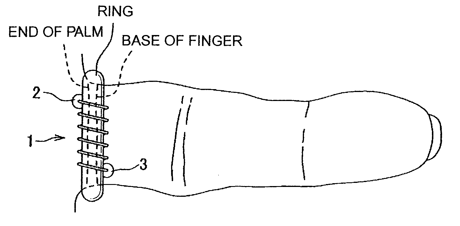
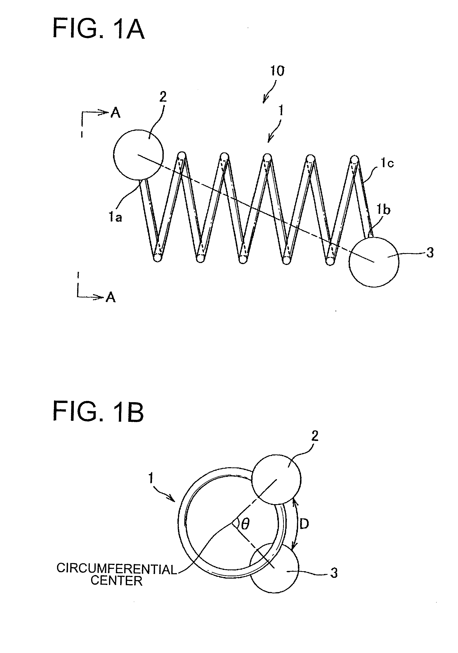
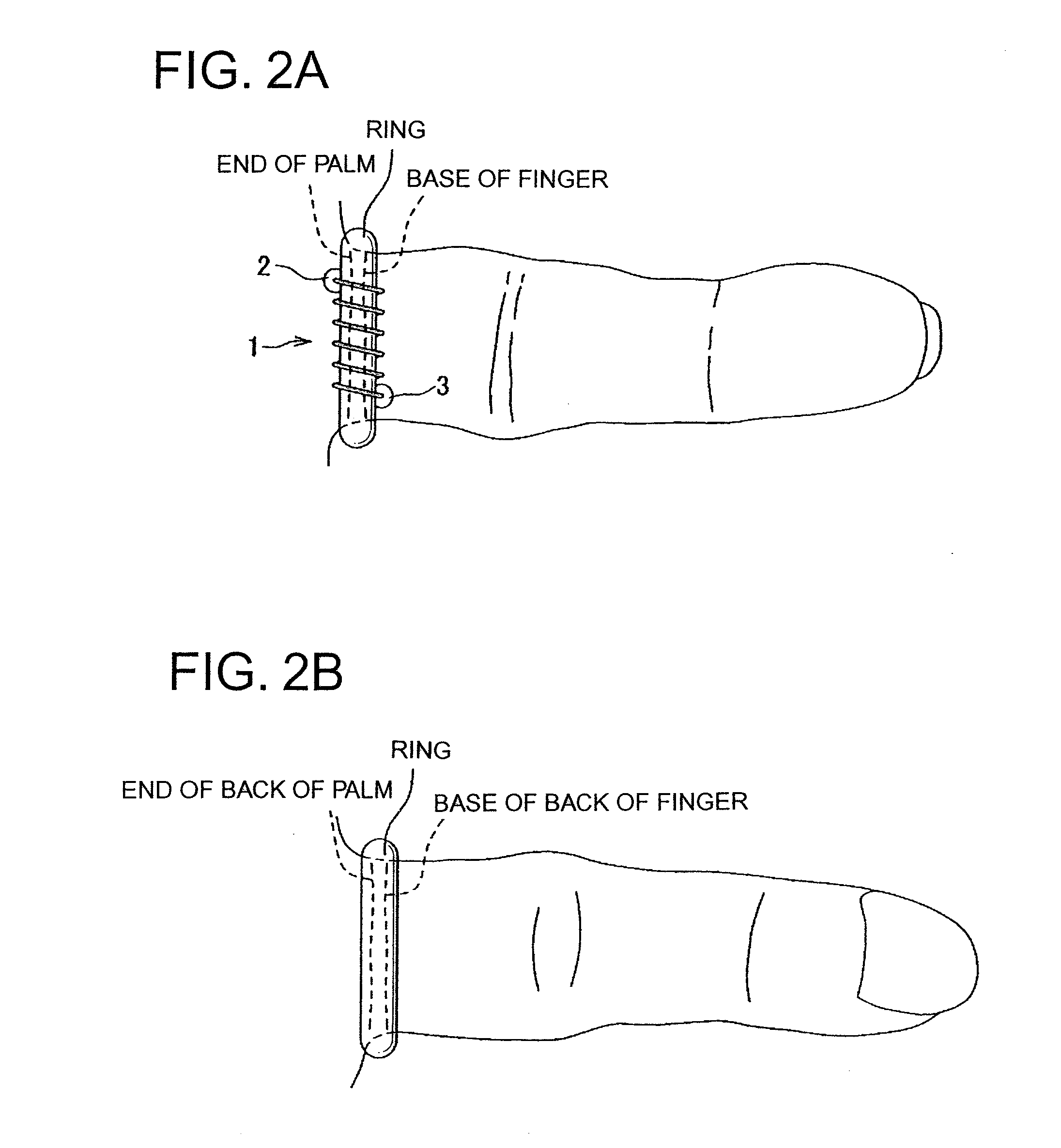
[0025]FIG. 1A shows a fitting device 10 for a ring according to the present invention. The fitting device 10 is provided with a coil (spring coil) 1, one stopper 2 and the other stopper 3. The coil 1 is a multi-turn coil made of a wire 1c. The coil 1 has an equal pitch and a constant coil diameter. The one stopper 2 is formed into a spherical body and is provided at one end 1a of the wire 1c, and the other stopper 3 is formed into a spherical body and is provided at the other end 1b of the wire 1c. As shown in FIG. 1B, for the fitting device 10 described above, the wire 1c and the one and the other stoppers 2, 3 are made of metal. The one stopper 2 and the other stopper 3 are arranged at an interval D along a circumference of the coil 1 when seen from an axis of the coil 1 (seen from a direction indicated by an arrow A shown in FIG. 1A). Furthermore, the one stopper 2 is arranged so as to be locat...


PUM


Abstract

There is provided a fitting device for a ring including: a multi-turned coil made of a metallic wire, the coil having equal pitch and constant coil diameter; one stopper formed into a spherical body and provided at one end of the wire; and the other stopper formed into a spherical body and provided at the other end of the wire. The one and the other stoppers are made of metal. The one and the other stoppers are arranged so that when seen from an axis of the coil, the one stopper and the other stopper are arranged at an interval along a circumference of the coil and so that the one stopper is located in the vicinity of an end of a palm and the other stopper is located in the vicinity of a base of a finger.

Description

CROSS REFERENCE TO RELATED APPLICATION[0001]The priority application Japan Patent Application No. 2010-268076 upon which this patent application is based is hereby incorporated by reference.BACKGROUND OF THE INVENTION[0002]1. Field of the Invention[0003]The present invention relates to a fitting device for a ring, by which a ring having the size larger than the size of a finger is easily retained to the finger.[0004]2. Description of the Related Art[0005]Conventionally, if the size of a ring is smaller than the size of a finger and thus the ring does not fit the finger, the ring can be enlarged using an expander. On the other hand, if the size of a ring is larger than the size of a finger, when such ring is put on the finger, the easily ring rotates and moves in the longitudinal direction of the finger. Thus, there is a problem that such rotation and the displacement of the ring needs to be prevented.[0006]One approach to solve the above-mentioned problem includes cutting and removi...

Claims


Application Information

Patent Timeline
Patent Type & Authority Applications(United States)
IPC IPC(8): A44C9/02
CPCA44C9/0084
Inventor TANAKA, NORIKO
Owner TANAKA NORIKO
Why Eureka
Try Eureka