Mounting structure for a direct injection fuel rail

a technology of mounting structure and fuel rail, which is applied in the direction of stress reducing fuel injection, fuel injection apparatus, charge feed system, etc., can solve the problem of fatigue stress applied to each component of the fuel rail

Active Publication Date: 2012-06-07
KEFICO
View PDF14 Cites 32 Cited by
  • Summary
  • Abstract
  • Description
  • Claims
  • Application Information

AI Technical Summary

Benefits of technology

[0007]The present invention provides a mounting structure for a direct injection fuel rail, capable of dispersing an impact applied to an injector cup due to a repulsive force when a fuel is injected, to a mount unit via a bridge as well as the fuel rail, or via only the bridge not the fuel rail, so as to prevent concentration of stress on a fuel rail due to displacement, to increase resistance against fatigue fracture, to prevent thermal deformation of the fuel rail and additional concentration of stress due to the thermal deformation, to improve manufacturability, and to easily ensure precise assembling positions.Technical Solution

Problems solved by technology

However, in that case, due to pressure, vibration, or heat generated by an engine, a fuel rail is displaced and thus a fatigue stress is applied to each component of the fuel rail.

Method used


Image

  • Mounting structure for a direct injection fuel rail
  • Mounting structure for a direct injection fuel rail
  • Mounting structure for a direct injection fuel rail

Examples


first embodiment

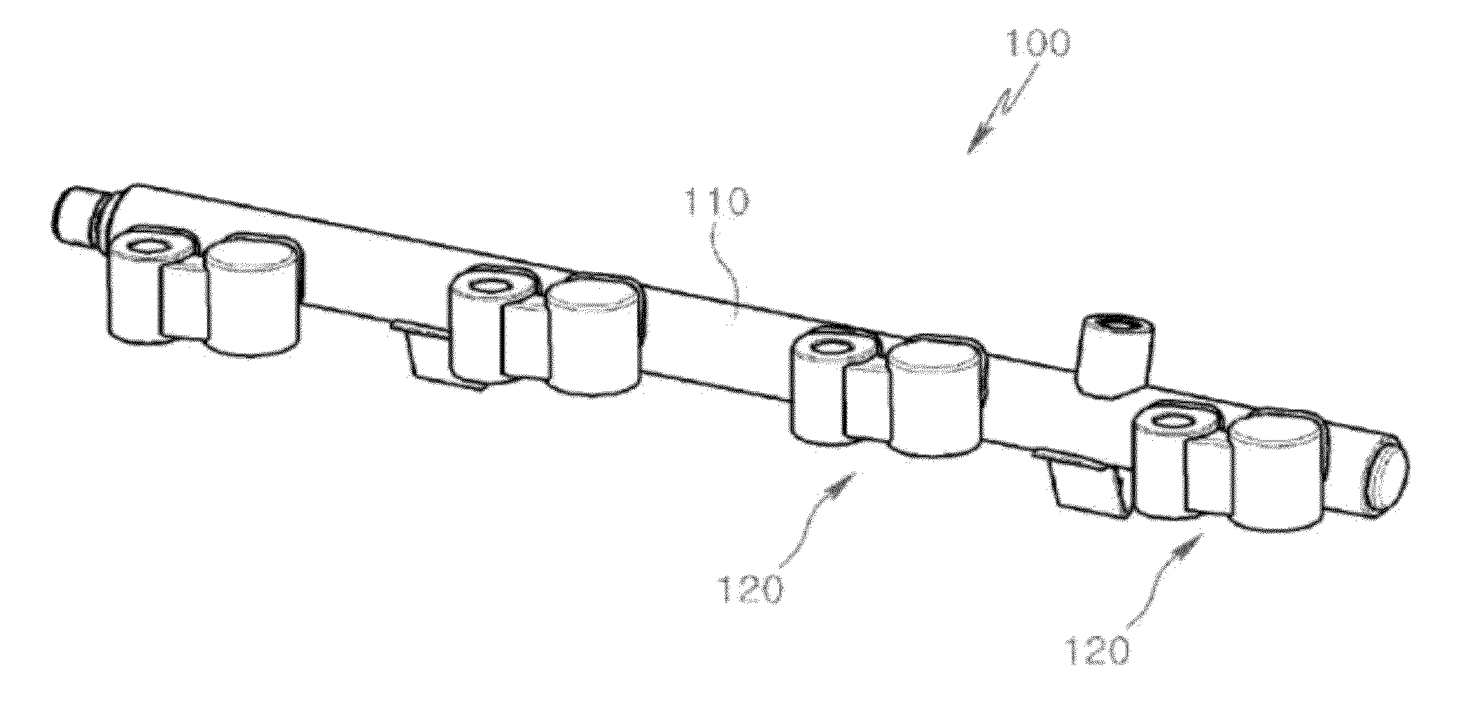
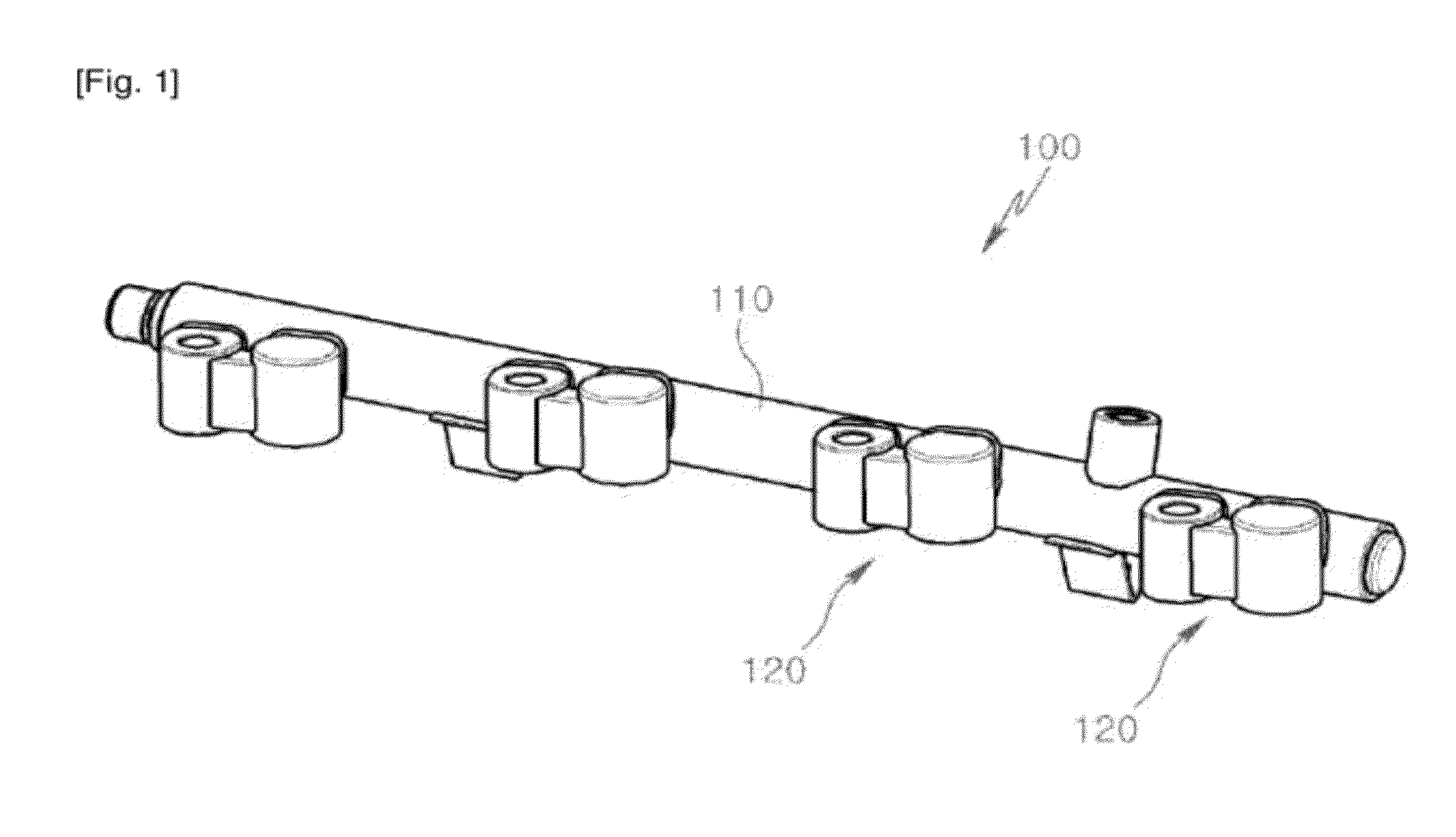
[0014]FIG. 1 is a perspective view of a direct injection fuel rail to which the present invention is applied.

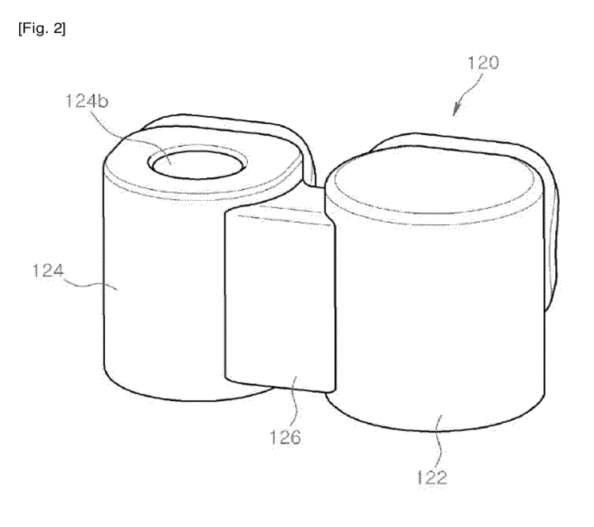
[0015]FIG. 2 is a perspective view of a mounting structure illustrated in FIG. 1 before it is bonded to the fuel rail.

[0016]FIG. 3 is a side view of the mounting structure illustrated in FIG. 2 toward the fuel rail.

[0017]FIG. 4 is a cross-sectional view cut along a line A-A illustrated in FIG. 3.

second embodiment

[0018]FIG. 5 is a perspective view of a direct injection fuel rail to which the present invention is applied.

[0019]FIG. 6 is a perspective view of a mounting structure illustrated in FIG. 5 before it is bonded to the fuel rail.

[0020]FIG. 7 is a side view of the mounting structure illustrated in FIG. 6 toward the fuel rail.

third embodiment

[0021]FIG. 8 is a perspective view of a mounting structure according to the present invention, before it is bonded to a fuel rail.

[0022]FIG. 9 is a side view of the mounting structure illustrated in FIG. 8 toward the fuel rail.

[0023]FIG. 10 is a cross-sectional view cut along a line B-B illustrated in FIG. 9.

[0024]FIGS. 11A through 11C are diagrams for comparing stresses between embodiments of the present invention and a comparative example.

[0025]FIGS. 12A through 12C are diagrams showing stress distributions corresponding to FIGS. 11A through 11C.


PUM


Abstract

The present invention relates to a mounting structure for a direct injection fuel rail. Specifically, a mounting structure 120 for a direct injection fuel rail comprises a mount unit 124 and an injector cup 122 combined with a main pipe 110, wherein the injector cup 122 and the mount unit 124 are connected to and integrated with each other via a bridge 126, wherein the injector cup 122 is bonded to the main pipe 110, and wherein the mount unit 124 is separated from the main pipe 110. As such, concentration of stress due to displacement may be prevented, resistance against fatigue fracture may be increased, thermal deformation and additional concentration of stress may be prevented, manufacturability may be improved, and precise assembling positions may be easily ensured.

Description

TECHNICAL FIELD [0001]The present invention relates to a mounting structure for a direct injection (gasoline direct injection, GDI) fuel rail.BACKGROUND ART [0002]Currently, various technologies are developed and applied to satisfy globally tightened exhaust gas regulations. In particular, research is being actively conducted on a gasoline direct injection (GDI) engine for directly injecting a high-pressure fuel into a combustion chamber so as to increase combustion efficiency, to reduce an exhaust gas, and to improve fuel efficiency and an output.[0003]A high-pressure pump and a direct injector for injecting a high-pressure fuel are already developed by a plurality of well-known companies, and a fuel rail for stably supplying a fuel into the direct injector (GDI) is being individually developed according to the position and space of an engine.[0004]In a multi port injection (MPI) or port fuel injection (PFI) engine for injecting a fuel into an intake port or valve, combining the fu...

Claims


Application Information

Patent Timeline
Patent Type & Authority Applications(United States)
IPC IPC(8): F02M55/02
CPCF02M55/025F02M61/14F02M2200/857F02M2200/8084F02M2200/856F02M2200/03F02M55/02F02M55/04
Inventor KWEON, MYEONG-HUNYOON, SUNG-HYUNJEON, SANG-HOON
Owner KEFICO
Why Eureka
Try Eureka