[0009]The particular
advantage of the invention is that through the offset height arrangement of the first upper strand and the second upper strand, an adequately
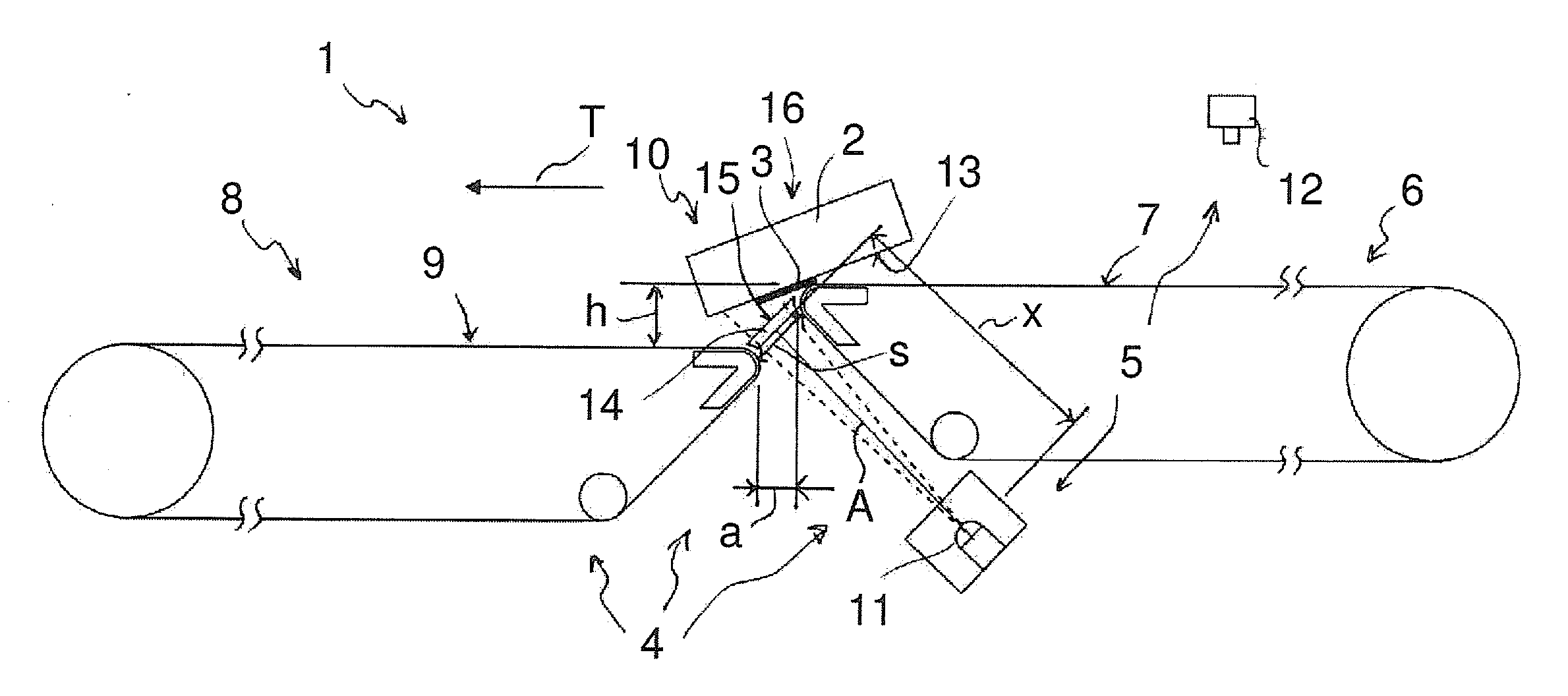
wide gap for scanning the underside of the object is created between the transport belts even if no, or only a very small, horizontal spacing is created between the first transport belt and the second transport belt. Said gap is defined essentially by a horizontal gap element. As a result, even small objects can be transferred reliably and safely from the first transport belt to the second transport belt. Completely automated recording of small objects is thus ensured.
[0010]In accordance with a preferred embodiment of the invention, the first transport belt and the second transport belt form a step in the area of the gap. The upper strand of the first transport belt is arranged above the upper strand of the second transport belt. By providing a step of this type, the object tips when it is transferred from the first transport belt to the second transport belt simply because of gravity, that is to say automatically. As a result, the transfer is particularly simple. No special components or subcomponents need to be provided for the transfer of the objects.
[0011]In accordance with a further development of the invention, an offset in height between the first upper strand and the second upper strand is selected such that, when a forward part of the object is transferred to the second transport belt, a rear part of the object is still supported on the first transport belt. A
free fall of the objects during the transfer is thus advantageously prevented. Mechanical stress on the object during the transfer is reduced so that damage to the object is prevented. Protection from damage is of great importance, particularly in the case of delicate objects, such as eggs, vegetables, porcelain and glassware.
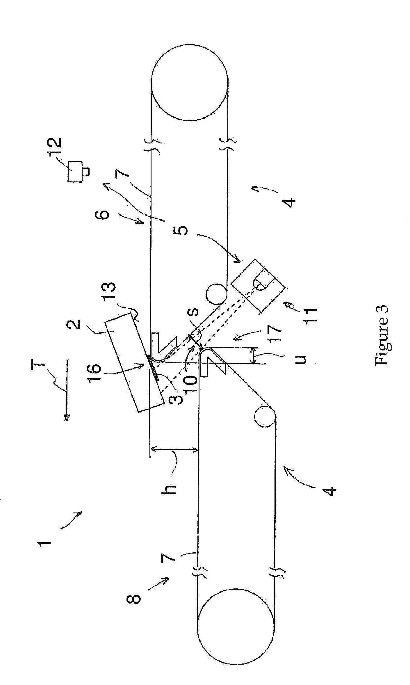
[0012]In accordance with a further development of the invention, the scanning element is arranged such that, by means of said element, the underside of the object in the tipped position can be scanned at least in sections. Advantageously, through an inclined arrangement of the scanning element, for example tipping said element relative to the vertical, the error rate of the scanning process can be reduced, and scanning of the machine-readable marking can be especially designed to be especially reliable. Furthermore, the horizontal spacing of the transport belts can be further reduced through the inclined arrangement of the scanning element.
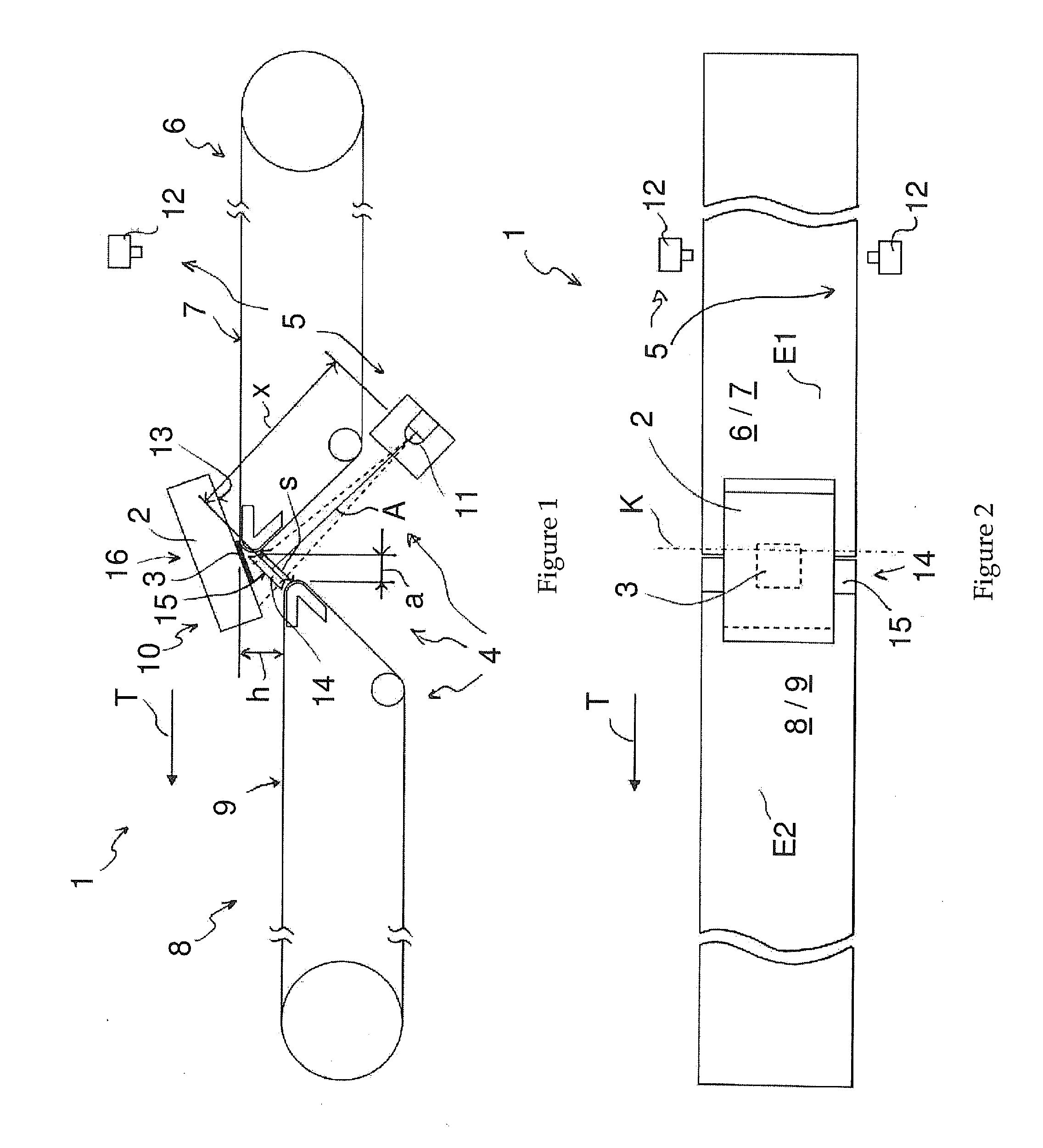
[0013]In accordance with a further development of the invention, the ends of the first transport belt and of the second transport belt facing each other in the transport direction can be arranged to overlap, at least in sections. A horizontal gap element is completely dispensed with as a result of the overlapping arrangement of the end faces. In this case, a horizontal overlap of said end faces is formed instead of a horizontal space between the first transport belt and the second transport belt. The overlap advantageously prevents particularly small objects from falling into the gap between the first transport belt and the second transport belt and being damaged or lost, or prevents said objects from damaging the scanning element arranged below the gap.
[0014]In accordance with a further development of the invention, an end of the second strand facing the first transport belt in the transport direction is located ahead of an end of the first transport belt facing the second transport belt. As a result, the gap has a horizontal gap element. Positioning of the scanning element on the side of the gap facing away from the object can be accomplished as a result in a particular simple manner.

