Sealed contact device

Active Publication Date: 2012-06-07
PANASONIC CORP
View PDF3 Cites 29 Cited by
  • Summary
  • Abstract
  • Description
  • Claims
  • Application Information

AI Technical Summary

Benefits of technology

[0048]As set forth above, the present invention has an effect of enabling the movable contact membe

Problems solved by technology

This leads to an increased friction force and hinders smooth movement of the movable contact membe

Method used


Image

  • Sealed contact device
  • Sealed contact device
  • Sealed contact device

Examples


Embodiment Construction

[0063]Hereinafter, an embodiment of the present invention will be described with reference to the accompanying drawings.

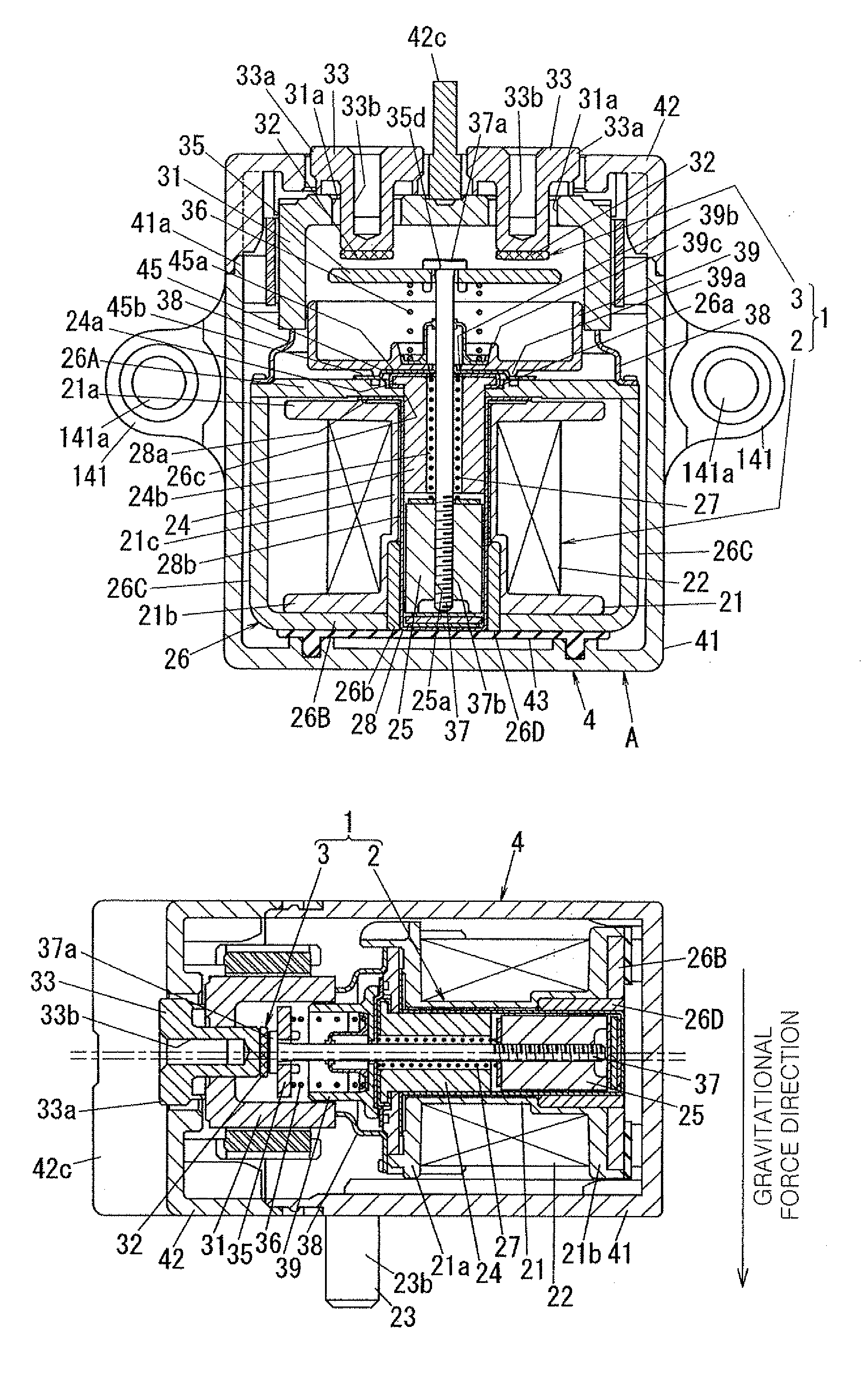
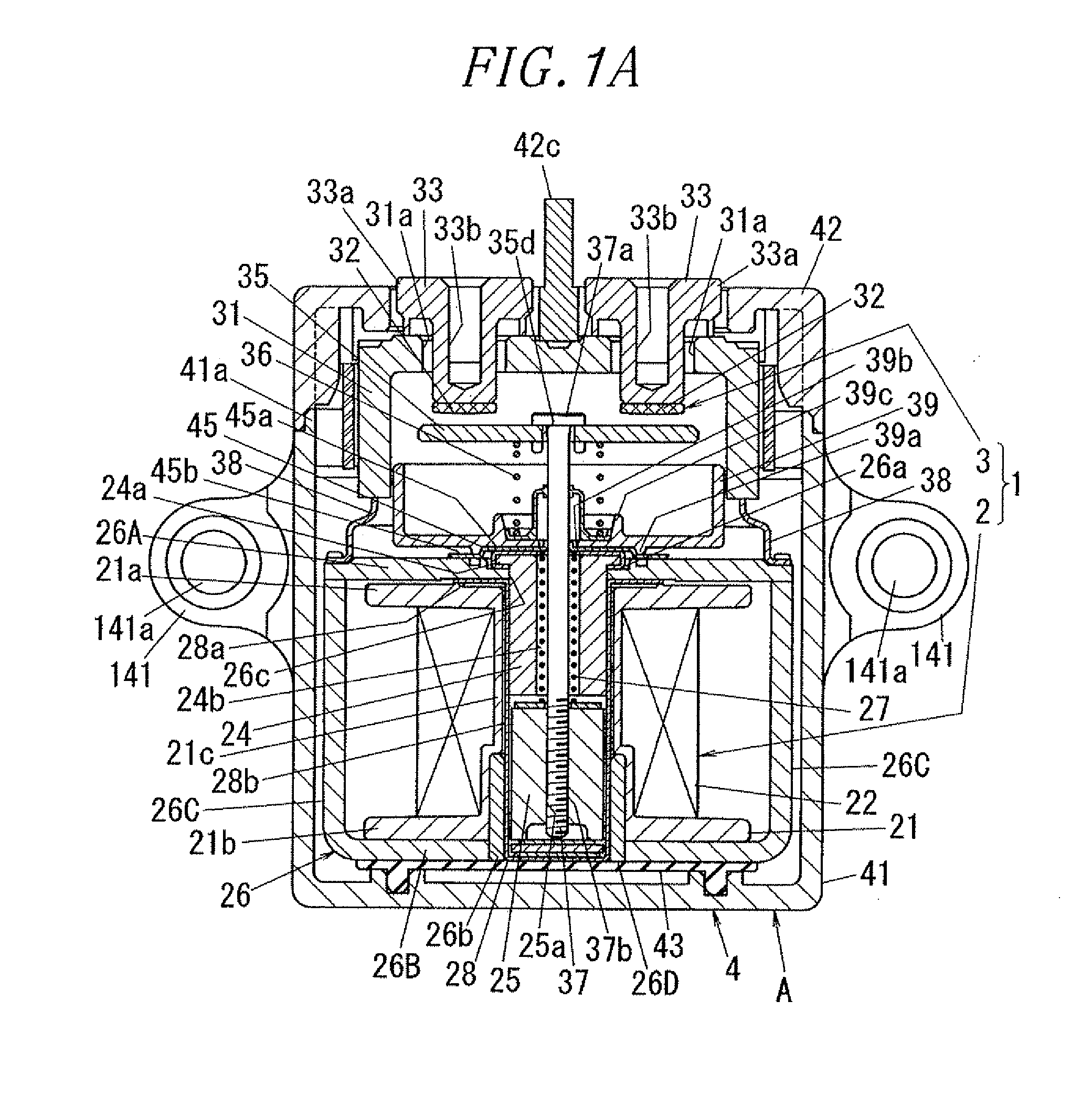
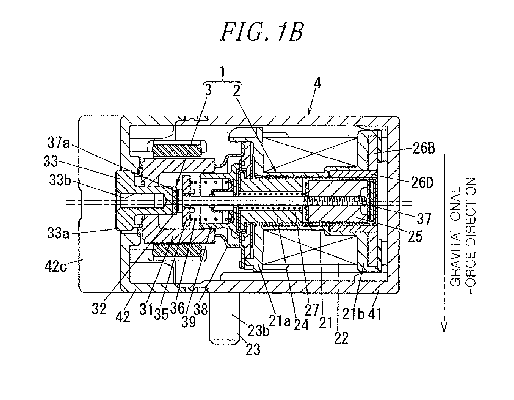
[0064]A sealed contact device A according to the present embodiment will be described with reference to FIGS. 1A, 1B, 2A, 25, 3A and 3B. In the following description, the up-down direction and the left-right direction in FIG. 1B will be defined as an up-down direction and a front-rear direction, respectively. The direction orthogonal to the up-down direction and the front-rear direction will be defined as left-right direction.

[0065]The sealed contact device A of the present embodiment differs from the conventional sealed contact device shown in FIGS. 8A and 8B in that the sealed contact device A of the present embodiment includes a movable contact member 35 having protrusions 35b and 35c differing in shape from the protrusions 135b and 135c of the movable contact member 135 of the conventional sealed contact device.

[0066]Referring to FIG. 2A, the sealed contact dev...


PUM


Abstract

A sealed contact device includes an electromagnet block 2 including a coil bobbin 21, a movable iron core 25, a yoke 26, and a return spring 27; a contact block 3 including a sealing container 31, fixed contact points 32, a movable contact member 35 arranged within the sealing container 31 and composed of a rectangular body portion 35a, first and second protrusions 35b, 35c formed in longitudinal sides of the body portion 35a and movable contact points 34, and a shaft 37; and a case 4. The first and second protrusions 35b, 35c of the movable contact member 35 are formed in non-point symmetry with respect to a connection portion of the movable contact member 35 and the shaft 37 so that, when the movable contact member 35 is rotated, only one of the first and second protrusions 35b, 35c makes contact with the sealing container 31.

Description

FIELD OF THE INVENTION[0001]The present invention relates to a sealed contact device.BACKGROUND OF THE INVENTION[0002]There is conventionally available a sealed contact device B which includes, as shown in FIGS. 8A, 8B, 9A, 9B and 10A through 10C, a hollow box-shaped case 4 and an inner block 1 arranged within the case 4, the inner block 1 having an electromagnet block 2 and a contact block 3 combined together (see, e.g., Japanese Patent Application Publication No. H11-238443). In the description given below, an up-down direction, a left-right direction and a front-rear direction orthogonal to the up-down direction and the left-right direction will be defined on the basis of the directions shown in FIG. 8A.[0003]The electromagnet block 2 includes a hollow cylindrical coil bobbin 21 made of an insulating material and wound with an exciting coil 22, a pair of coil terminals 23 connected to the opposite end portions of the exciting coil 22, a stationary iron core 24 fixed to the inside...

Claims


Application Information

Patent Timeline
IPC IPC(8): H01H50/54
CPCH01H50/023H01H50/045H01H1/66H01H51/065H01H2050/025H01H50/546H01H50/14H01H50/54
Inventor YAMAGATA, KATSUTOSHINISHIMURA, TSUKASAYAMAMOTO, RITUYOSITANI, KATUMIITO, MASAHIRO
Owner PANASONIC CORP
Why Eureka
Try Eureka