Monolithic Geared Optical Reflector

Inactive Publication Date: 2012-06-07
THERMO ELECTRON SCI INSTR
View PDF6 Cites 61 Cited by
  • Summary
  • Abstract
  • Description
  • Claims
  • Application Information

AI Technical Summary

Benefits of technology

[0009]Accordingly, the present invention provides a monolithic geared optical reflector that can be configured as a system that allows the configured reflector to poi

Problems solved by technology

Conventional optical rotating mirror systems however, show difficulty in accurately placing beams at variable positions while maintaining a fixed angle of incidence upon

Method used


Image

  • Monolithic Geared Optical Reflector
  • Monolithic Geared Optical Reflector
  • Monolithic Geared Optical Reflector

Examples


working examples

NON-LIMITING WORKING EXAMPLES

Source Mirror Rotation Example

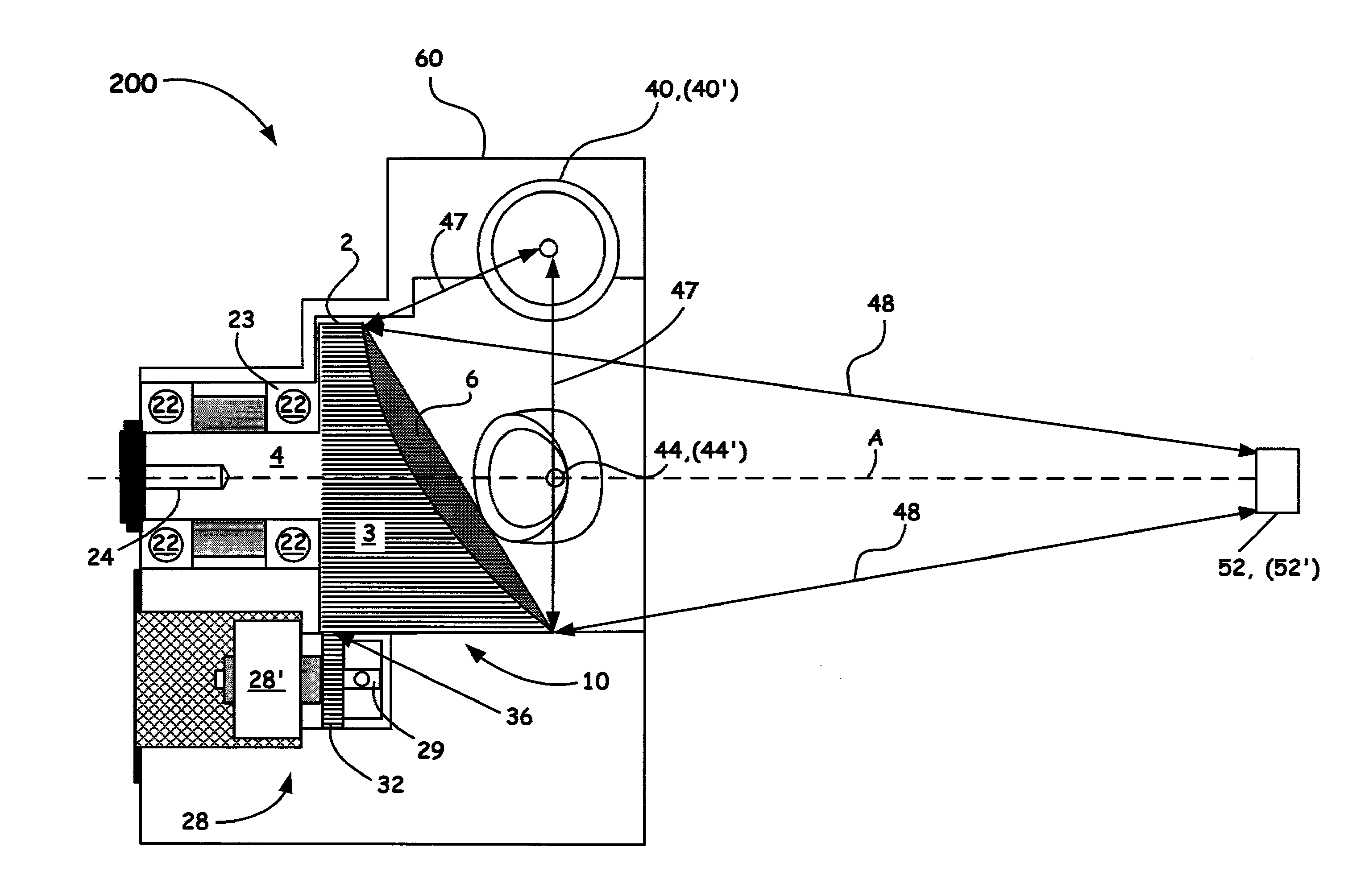
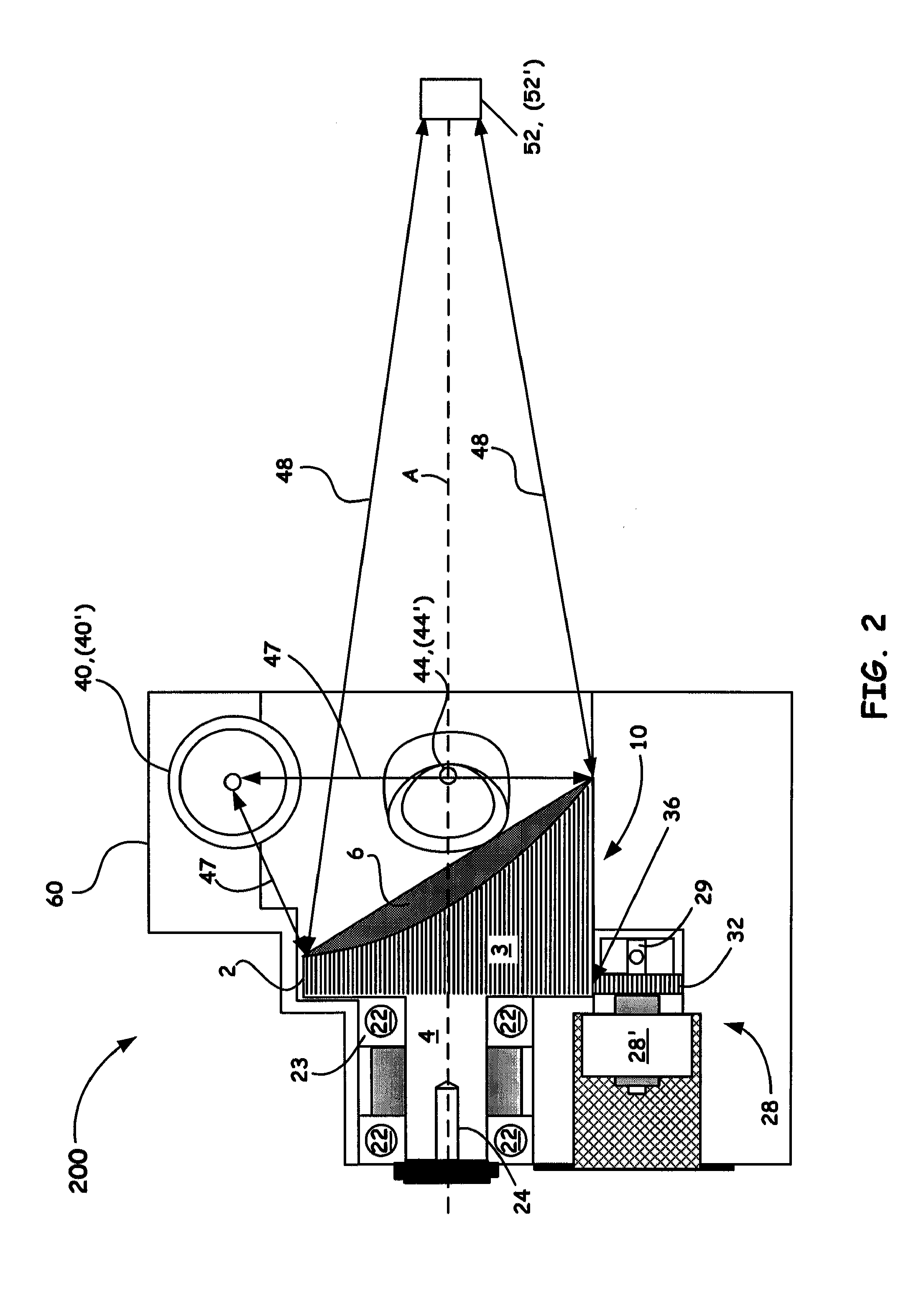
[0033]Again turning to FIG. 2, it is to be again noted that the curvature configured for reflective surface 6 is elliptical to illustrate the principles of an example embodiment of the present invention. Accordingly, the example surface configured for the monolithic geared reflector 10 comes with a prescribed degree of eccentricity to enable desired primary and secondary foci positions, e.g., foci F1 and F2 as discussed above with respect to an elliptical configuration for FIG. 2. Multiple sources 40, 44 (e.g., sources configured to produce different or same bands of optical radiation ranging from the ultra-violet (UV) through the Visible up to the far-IR) are thus configured about monolithic geared reflector 10 in a predetermined manner dependent upon system constraints that include the curvature of surface 6. The sources 40, 44, in the case of infrared (IR) applications (e.g., FTIR) can be a lamp, or a heated infrared sour...


PUM


Abstract

A novel monolithic geared optical reflector apparatus which is configured from a gear blank machined to have an integral shaft and integral reflective surface with desired optical properties is introduced herein. Such a rotating mirror device is beneficially capable of being configured into any optical instrument, such as, but not limited to a spectrophotometer, wherein the reflector is adapted to accurately point to a plurality of locations within or out of the system via gear to gear rotation.

Description

BACKGROUND OF THE INVENTION[0001]1. Field of the Invention[0002]The present invention relates to reflector rotating assemblies within an optical instrument. More specifically, the present invention relates to an optical component configured as a monolithic geared reflector which by design can direct optical radiation to multiple locations within a spectrophotometer instrument in a time efficient manner and with improved accuracy.[0003]2. Discussion of the Related Art[0004]Crucial to any optical system is the ability to adjust the beam pointing, whether incoming or outgoing. Optical beams within, for example, a spectrophotometer instrument, are conventionally directed to one or more positions, such as detector positions, by redirecting light using one or more fixed and / or moveable mirrors. The moveable mirrors in such an instrument are often moved linearly or rotated with respect to a given axis of the optical beam path to enable directing the reflected beam to a given location in ac...

Claims


Application Information

Patent Timeline
IPC IPC(8): G01J3/42G02B26/08
CPCG01J3/0202G02B26/0816G01J3/0237G01J3/021
Inventor CLEARY, JOSEPH A.
Owner THERMO ELECTRON SCI INSTR
Why Eureka
Try Eureka