
Battery pack for suppressing deviation of central battery cell and vehicle including the same

Inactive Publication Date: 2012-06-07
SANYO ELECTRIC CO LTD
View PDF3 Cites 22 Cited by
  • Summary
  • Abstract
  • Description
  • Claims
  • Application Information

AI Technical Summary

Benefits of technology

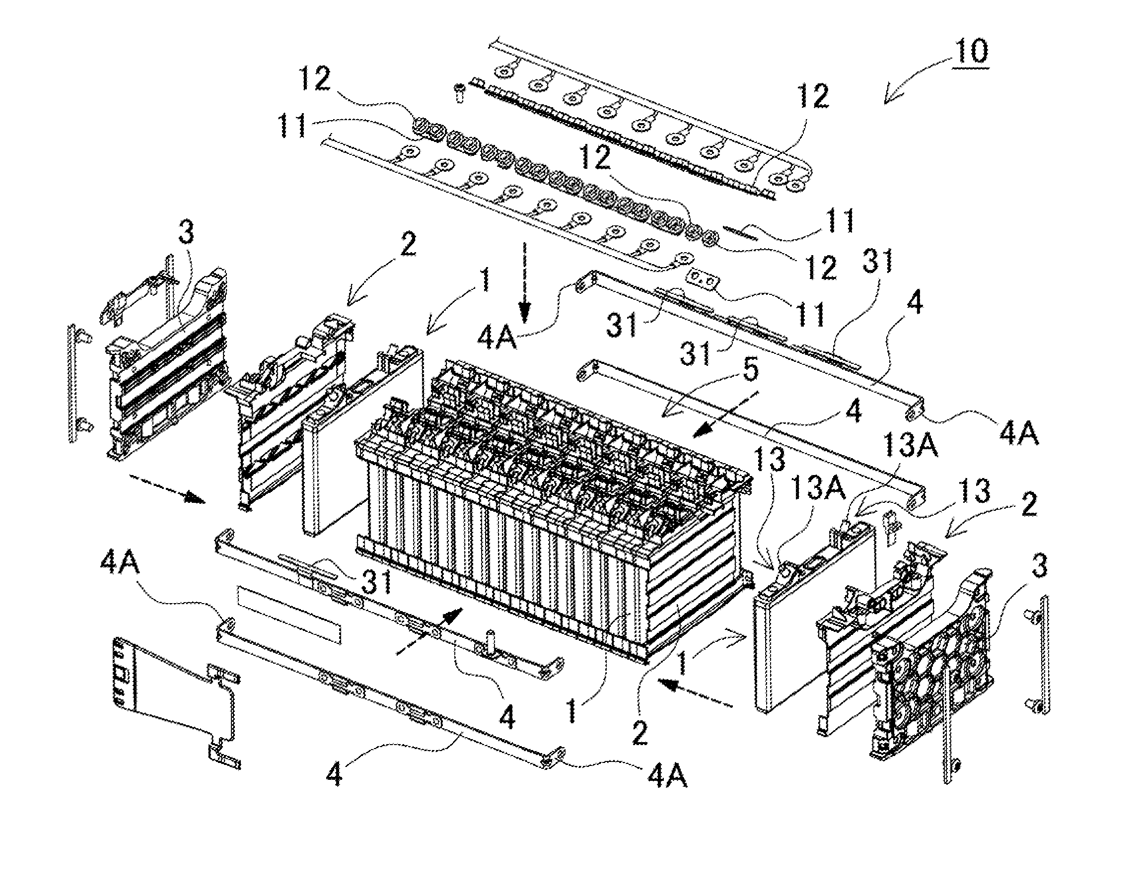
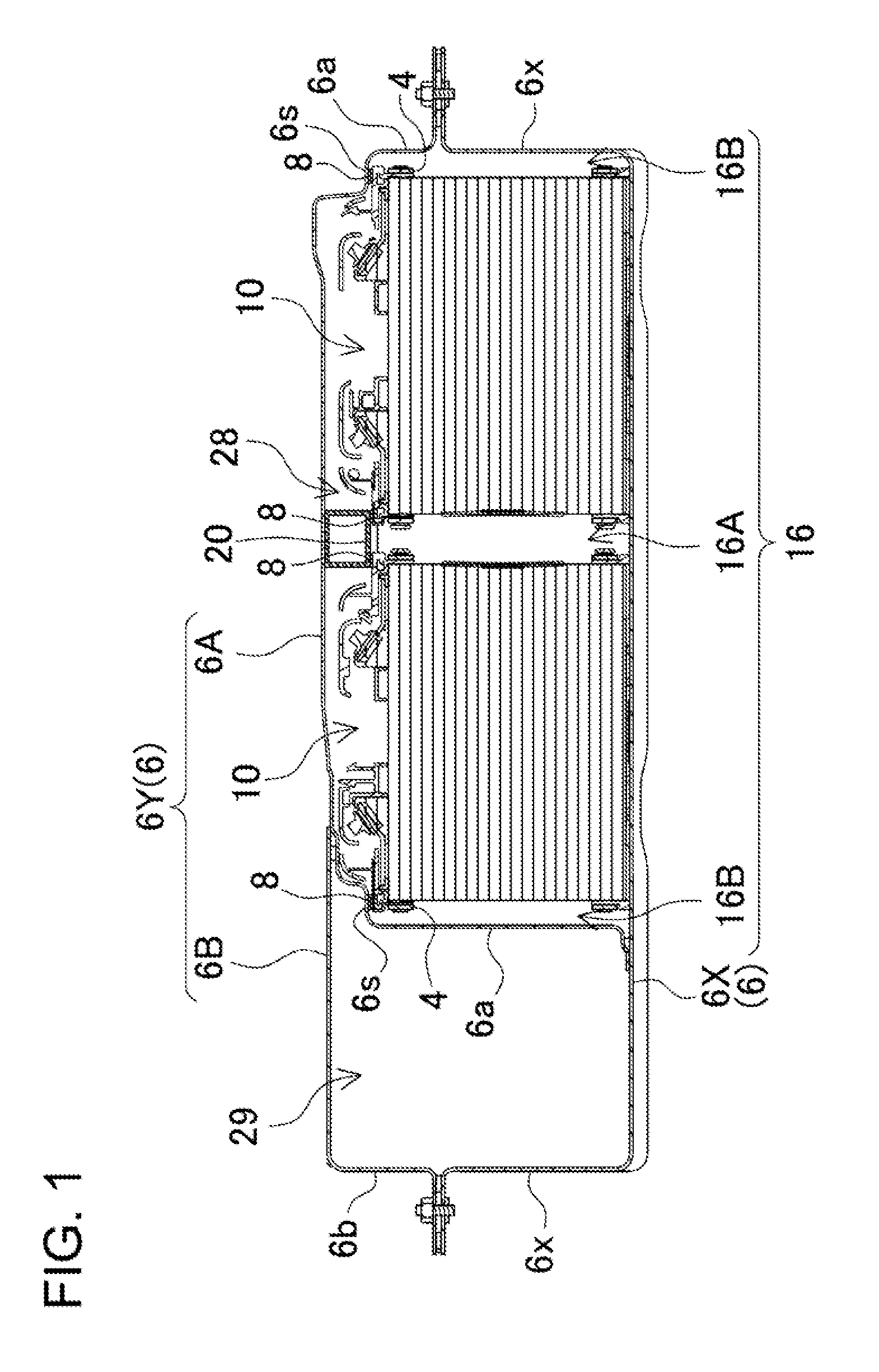
[0012]According to the thus-constructed battery pack, when the battery pack is secured onto a horizontal surface, it is possible to prevent vertical deviation of the at least one of the battery cells, which is located in a central part of the battery pack. Accordingly, the plurality of battery cells can be held coplanar. Therefore, it is possible to keep the coupled state of the battery cells, and to improve reliability.
[0039]Therefore, it is possible to suppress positional deviation of the battery cells, which are coupled to each other by the bind bar.

Problems solved by technology

Particularly, in the case where the battery pack is used for vehicles, the battery pack will be subjected to vibration and shock.
It is difficult for the thus-constructed battery pack to reliably prevent vertical vibration of the battery cells which are held side by side by the bind bars.
Particularly, in the case where the battery pack is used in a vibration environment such as vehicle environment, it is hard to reliably prevent the vibration of the battery cells.
If the central battery cells are thus vibrated, various defects may occur.
As a result, the electrically-insulating layer may be damaged, which in turn causes puncture or short circuit.
In addition, vibration may physically damage the battery cells, and may deteriorate the electrical characteristics of the battery cells or reduce battery cell life.
Thus, vibration may cause these defects.
Particularly, in the case of vehicle power supply device, vibration and shock may cause vertical deviation of battery cells over the course of use.
If the central battery cells are deviated upward, a stress will be applied to a connection part between the electrode terminal and the sealing plate, which may cause cracks or rupture.

Method used


Image

  • Battery pack for suppressing deviation of central battery cell and vehicle including the same
  • Battery pack for suppressing deviation of central battery cell and vehicle including the same
  • Battery pack for suppressing deviation of central battery cell and vehicle including the same

Examples


Embodiment Construction

)

[0061]The following description will describe embodiments according to the present invention with reference to the drawings. It should be appreciated, however, that the embodiments described below are illustrations of a battery pack and an electrically-driven vehicle including this battery pack to give a concrete form to technical ideas of the invention, and a battery pack and an electrically-driven vehicle including this battery pack of the invention are not specifically limited to description below. Furthermore, it should be appreciated that the members shown in claims attached hereto are not specifically limited to members in the embodiments. Members same as or similar to those of this invention are attached with the same designation and the same reference numerals and their description is omitted. In addition, a plurality of structural elements of the present invention may be configured as a single part that serves the purpose of a plurality of elements, on the other hand, a si...


PUM


Abstract

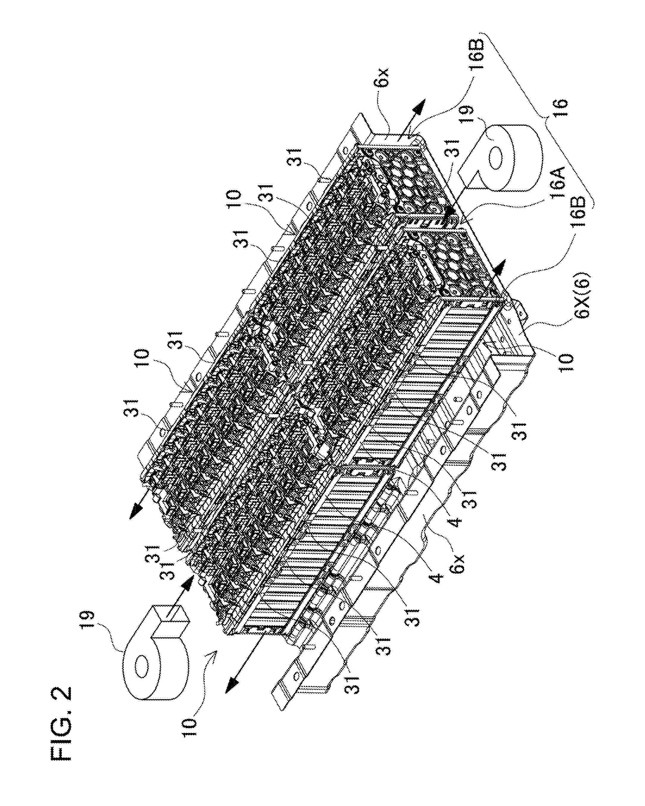
A battery pack device includes a plurality of battery cells 1, a bind bar 4, and a regulation member 31. The plurality of battery cells 1 has a rectangular box exterior shape. The bind bar 4 couples the plurality of battery cells 1 to each other with the battery cells 1 being arranged side by side. When the battery pack 10 is secured onto a horizontal surface, the regulation member 31 regulates upward deviation of at least one of the battery cells 1, which is located in a central part of the battery pack in the side-by-side arrangement direction of the battery cells 1.

Description

BACKGROUND OF THE INVENTION[0001]1. Field of the Invention[0002]The present invention relates to a battery pack including a plurality of rectangular-box-shaped battery cells, and in particular to a battery pack to be used as a power supply device for electric motors for driving vehicles such as hybrid cars and electric vehicles. In addition, the present invention relates to an electrically-driven vehicle including this battery pack.[0003]2. Description of the Related Art[0004]Electric vehicles and hybrid cars are known. Electric vehicles are driven by an electric motor. Hybrid cars are driven by an electric motor and an internal-combustion engine. These types of cars include a power supply device which includes battery cells accommodated in an exterior case. In order to provide enough power to drive the cars by means of an electric motor, such a power supply device includes a number of battery cells serially connected to each other for increasing output voltage. For example, a batte...

Claims


Application Information

Patent Timeline
IPC IPC(8): H01M2/10H01M10/60H01M10/613H01M10/625H01M10/647H01M10/6556H01M10/6563H01M50/209H01M50/224H01M50/264H01M50/276H01M50/293
CPCH01M2/1077Y02E60/10H01M50/293H01M50/224H01M50/209H01M50/264H01M50/276
Inventor OKADA, WATARUNAKAMURA, SHINSUKEOHMURA, TOMOYUKIWAKABAYASHI, AKINOBU
Owner SANYO ELECTRIC CO LTD
Learn More