Detection device, electronic apparatus, and robot

a detection device and electronic technology, applied in the direction of force/torque/work measurement apparatus, instruments, manufacturing tools, etc., can solve the problems of inability to measure the force in the in-plane direction (slipping force) on the measurement face, the force receiving sheet is not easy to operate, and the computation amount is large, so as to achieve high precision

Inactive Publication Date: 2012-06-14
COLUMBIA PEAK VENTURES LLC
View PDF5 Cites 25 Cited by
  • Summary
  • Abstract
  • Description
  • Claims
  • Application Information

AI Technical Summary

Benefits of technology

[0033]With such a configuration, since the detection device described above is included, it is possible to provide a robot that is able to detect the presence of external force quickly and detect the direction and the magnitude of the external force with high precision.

Problems solved by technology

However, with the detection device of JP-A-60-135834 described above, since the transformation amounts of the protrusions are computed from an image that is imaged by a camera, the computation amount is large and the time taken for force detection is long.
Further, it is not possible to measure the force in the in-plane direction (slipping force) on the measurement face (back face) of the force receiving sheet.
As described above, with the detection devices of JP-A-60-135834 and JP-A-2008-164557, there was a problem that neither could combine the function of detecting the presence of force quickly and the function of detecting the distribution or the direction and the magnitude of external force with high accuracy.

Method used


Image

  • Detection device, electronic apparatus, and robot
  • Detection device, electronic apparatus, and robot
  • Detection device, electronic apparatus, and robot

Examples


first embodiment

Configuration of Detection Device

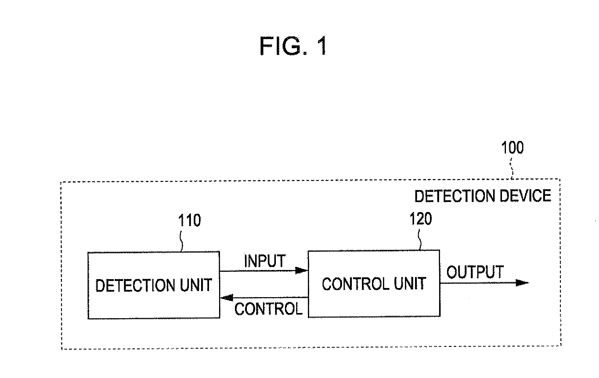
[0059]FIG. 1 is a block diagram that illustrates an electric configuration of a detection device. The electric configuration of the detection device will be described below with reference to FIG. 1.

[0060]As illustrated in FIG. 1, a detection device 100 includes a detection unit 110 and a control unit 120. The detection unit 110 includes a contact sensor 12 as the first sensor for detecting the presence of force (refer to FIG. 2) and force sensors 13 as the second sensors for detecting the magnitude of the force (refer to FIG. 2). Further, the information that is detected by the detection unit 110 is input to the control unit 120.

[0061]The control unit 120 performs the action of detecting the presence of external force by the contact sensor 12 and controls the next detection action of the force sensors 13 based on the detection result.

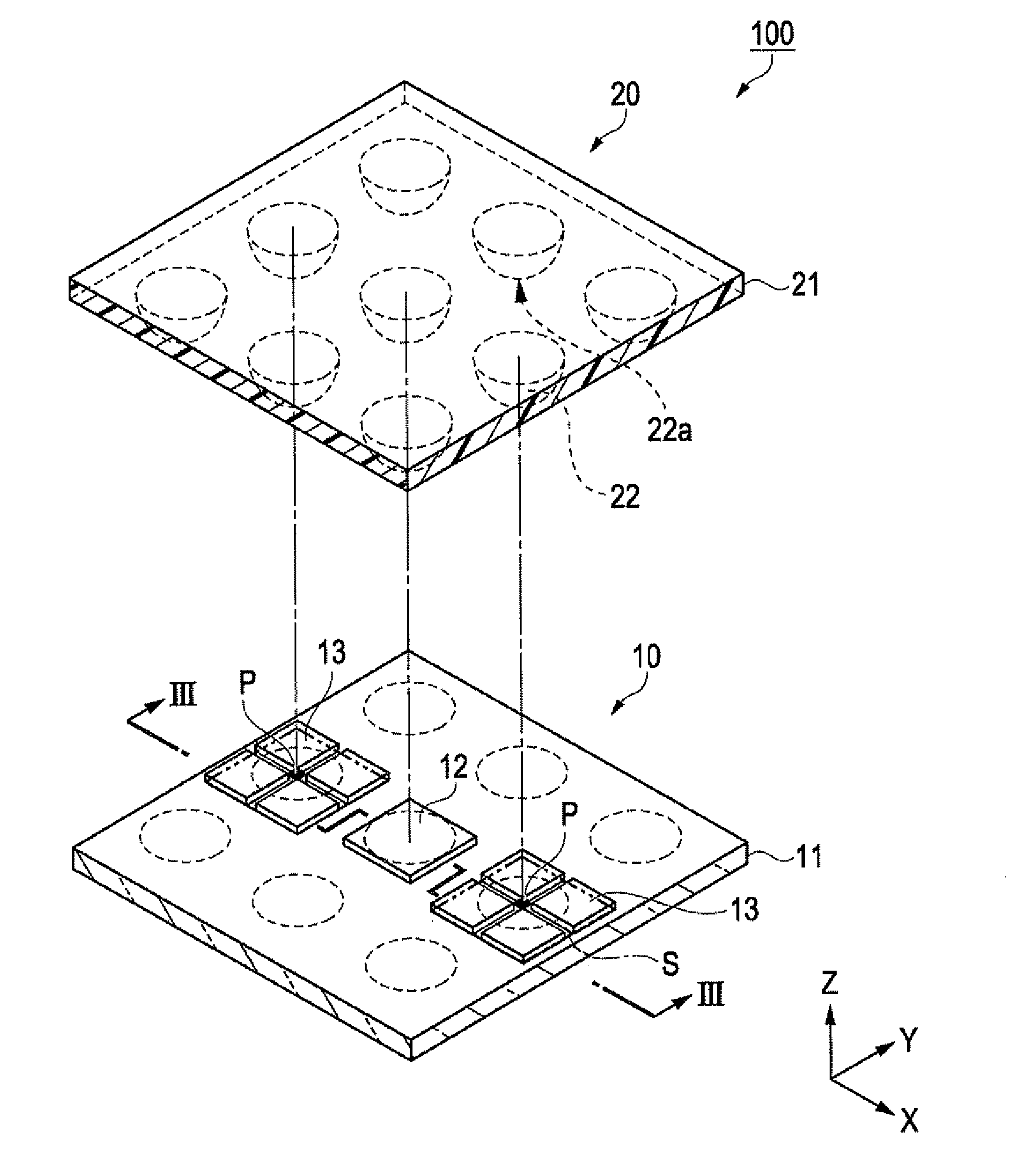
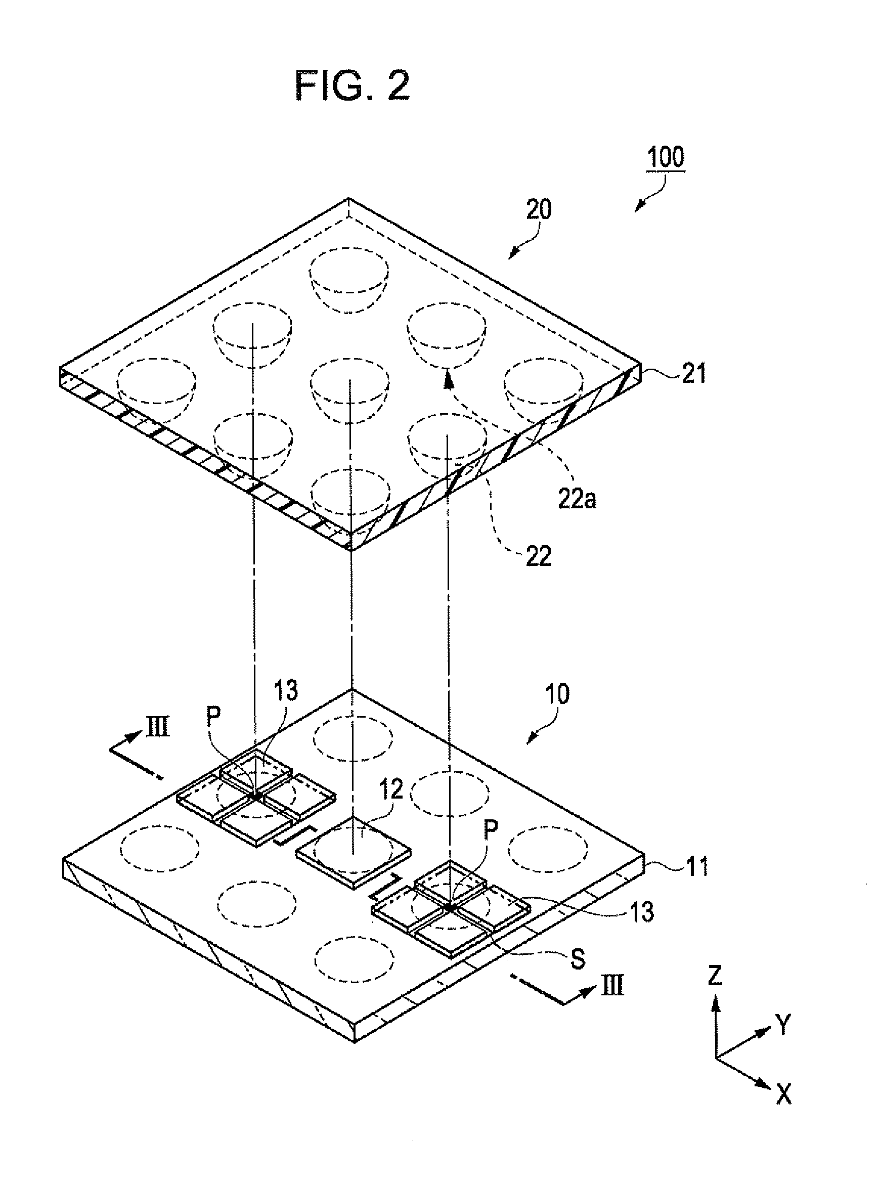
[0062]FIG. 2 is an exploded perspective diagram that illustrates a configuration of the detection device. FIG. 3 is a ...

second embodiment

Configuration of Detection Device

[0130]FIG. 11 is a block diagram that illustrates a detection device according to a second embodiment. The configuration of the detection device according to the second embodiment will be described below with reference to FIG. 11.

[0131]Similarly to the first embodiment, a detection device 200 of the second embodiment includes the detection unit 111 that detects external force that is applied on a plurality of force sensors 113 (refer to FIG. 12), and the control unit 120 that performs a detection action of detecting the presence of external force from the force values that are detected by a portion out of the plurality of force sensors 113 and which controls the next detection action of the detection unit 111 from the detection result.

[0132]FIG. 12 is an exploded perspective diagram that illustrates an outline configuration of the detection device of the second embodiment corresponding to FIG. 2. FIG. 13 is a schematic cross-sectional diagram along a...

third embodiment

Electronic Apparatus

[0159]FIG. 17 is a schematic diagram that illustrates an outline configuration of a mobile phone on which either of the detection devices of the embodiments described above is applied. A mobile phone 1000 as an example of an electronic apparatus includes a plurality of operation buttons 1003, a control pad 1002, and a liquid crystal panel 1001 as a display unit. By operating the control pad 1002, the screen to be displayed on the liquid crystal panel 1001 is scrolled. A menu button (not shown) is displayed on the liquid crystal panel 1001. For example, by meeting a cursor (not shown) on the menu button and pressing hard on the control pad 1002, a phonebook is displayed or the phone numbers on the mobile phone 1000 are displayed.

[0160]FIG. 18 is a schematic diagram that illustrates an outline configuration of a mobile information terminal (PDA: Personal Digital Assistants) on which either of the detection devices according to the embodiments described above is app...


PUM

PropertyMeasurementUnit
radiusaaaaaaaaaa
heightaaaaaaaaaa
sizeaaaaaaaaaa

Abstract

A detection unit includes a sensor that detects the presence of force and a force component separation mechanism that separates the magnitude and the direction of the force and a control unit that controls the detection action of the force component separation mechanism based on the detection result of the sensor.

Description

BACKGROUND[0001]1. Technical Field[0002]The present invention relates to a detection device, an electronic apparatus including the detection device, and a robot.[0003]2. Related Art[0004]The detection devices described in JP-A-60-135834 and JP-A-2008-164557 are known detection devices which detect an external force. The application of such detection devices to touch panels, contact sensors on robots, and the like is being investigated.[0005]The detection device of JP-A-60-135834 has a configuration of using a force receiving sheet, on the back face of which conic protrusions are arranged substantially evenly, and detecting force distribution from the transformation amounts of the protrusions. The detection device of JP-A-2008-164557 includes contacts that are displaceable on the front face, and includes a plurality of force-sensitive elements that detect and output the displacements of the contacts using detection points.[0006]However, with the detection device of JP-A-60-135834 des...

Claims


Application Information

Patent Timeline
Patent Type & Authority Applications(United States)
IPC IPC(8): G01L1/04G01L1/20B25J19/02G06F3/038G06F3/041
CPCG01L1/04G01L1/20Y10S901/46G01L5/228G06F3/03547G01L5/161B25J13/085G06F3/0338G06F3/0414G01L1/205G06F3/04144
Inventor IKEBE, TOMOUTSUNOMIYA, SUMIO
Owner COLUMBIA PEAK VENTURES LLC
Why Eureka
Try Eureka