Eureka AIR delivers breakthrough ideas for toughest innovation challenges, trusted by R&D personnel around the world.

Apparatus and method for enhanced heat transfer

a technology of enhanced heat transfer and apparatus, applied in the field of thermal management technology, can solve the problems of incompatibility of two-phase heat transfer systems with microelectronic packages, limitations to the current state of two-phase cooling, and phase change that greatly increases the heat flux from the heated surface, so as to achieve the effect of dissipating more energy

Inactive Publication Date: 2012-06-14
NUVENTIX +1
View PDF10 Cites 16 Cited by
  • Summary
  • Abstract
  • Description
  • Claims
  • Application Information

AI Technical Summary

Benefits of technology

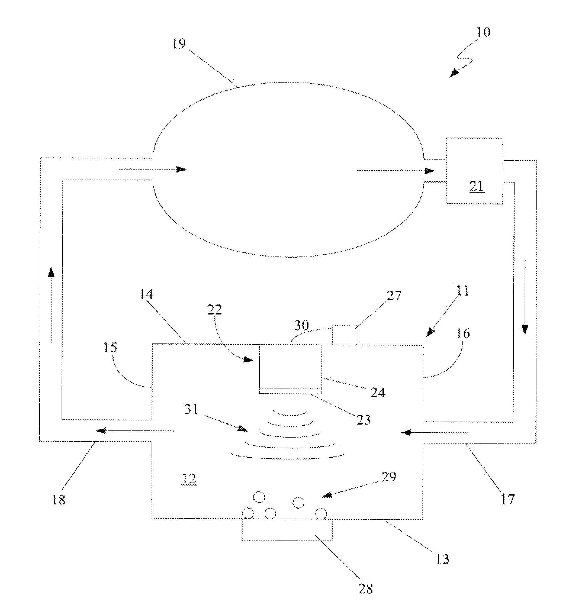
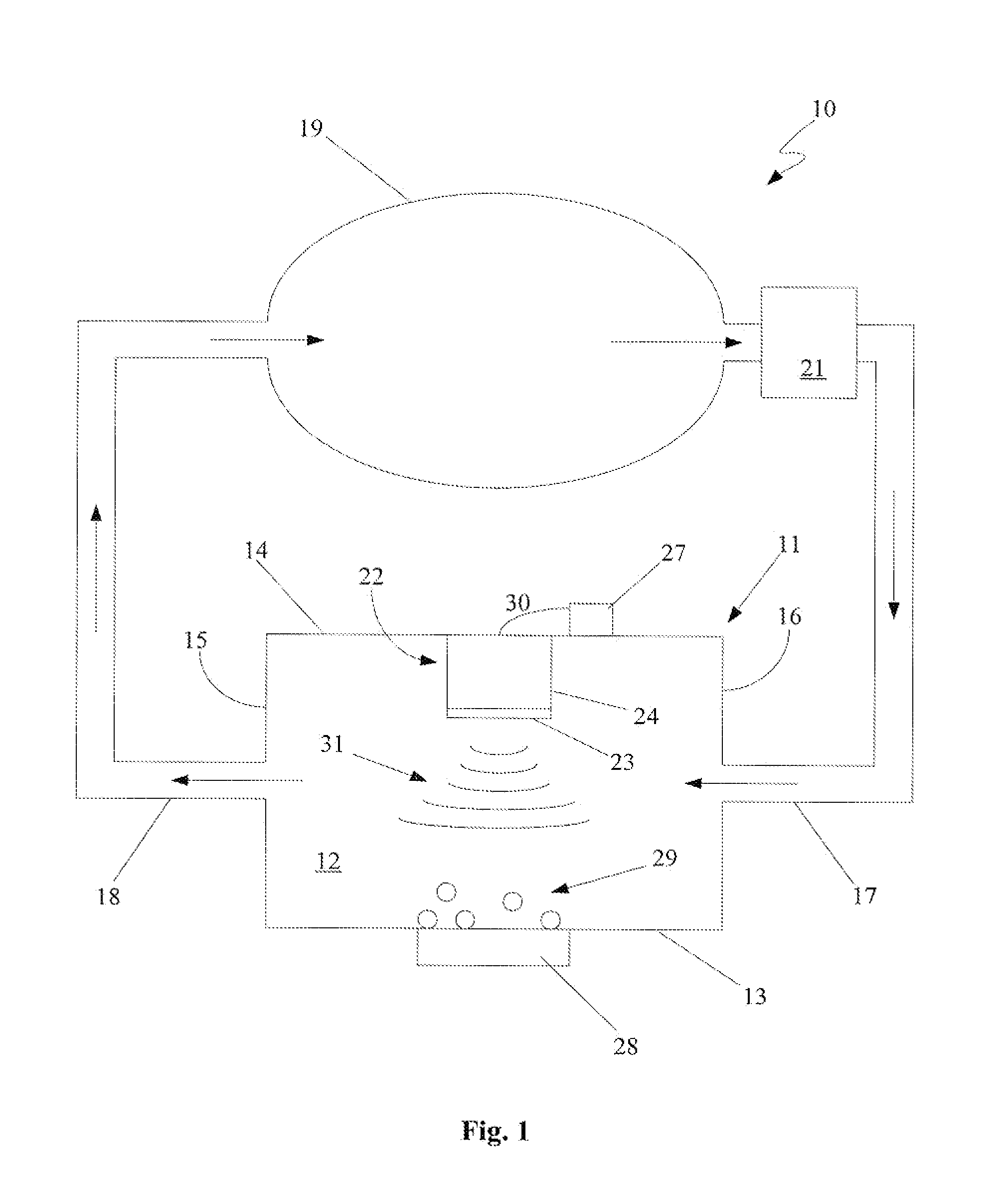
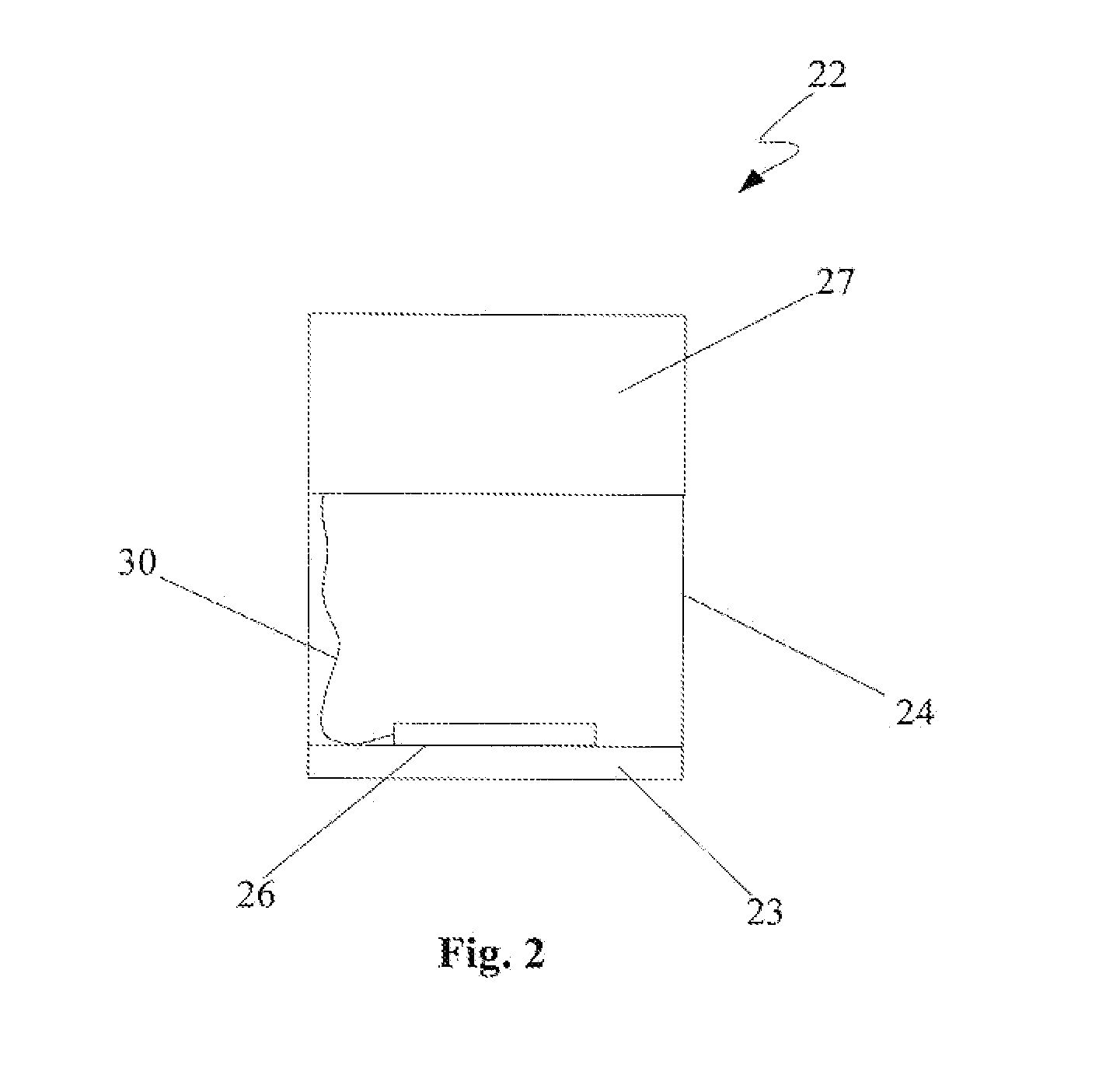
The present invention provides a system and method for cooling heated bodies and environments using a vibration-induced bubble injection system. The device uses small vapor bubbles attached to a solid surface and delays the onset of the critical heat flux, resulting in improved cooling performance compared to traditional methods. The device includes a chamber containing a fluid, a heated wall, and an actuator that emits pressure vibrations to dislodge the vapor bubbles from the heated wall. The method involves generating heat in the wall, causing the formation of vapor bubbles, and emitting pressure vibrations into the fluid, wherein the vapor bubbles dislodge from the heated wall due to the pressure vibrations. The invention has various applications, such as cooling electronic devices and improving cooling efficiency in power generation systems.

Problems solved by technology

Thermal management is recognized as a major challenge in the design and packaging of state-of-the-art integrated circuits in single-chip and multi-chip modules.
First, the liquid to vapor phase change greatly increases the heat flux from the heated surface.
There are limitations to the current state of the art in two-phase cooling.
First, two-phase heat transfer systems have traditionally been viewed as incompatible with microelectronic packages.
When the heat flux from the surface is increased past a critical level, a large, potentially catastrophic increase in temperature occurs.
In film boiling, a thin insulating layer of vapor completely covers the heated surface, which then produces a large temperature increase.
Thus, the performance of immersion cooling in this environment is drastically reduced.
A heretofore unaddressed need exists in the industry to address the aforementioned deficiencies and inadequacies.
The VIBE device described below exceeds the performance of conventional immersion cooling devices because it delays the onset of the critical heat flux.

Method used


Image

  • Apparatus and method for enhanced heat transfer
  • Apparatus and method for enhanced heat transfer
  • Apparatus and method for enhanced heat transfer

Examples


embodiment 10

[0025]The chamber 11 could be constructed of any suitable material. Generally, the material used for the chamber 11 will depend to some degree on the particular fluid 12 in the chamber 11 and on the particular heat transfer characteristics desired. The preferred material from which the chamber 11 is to be constructed is a light-weight metallic material from which the chamber 11 can be easily and inexpensively manufactured. For example, the material for the chamber 11 of the present embodiment 10 is aluminum.

[0026]In the present embodiment 10, the entire chamber 11 is constructed from an aluminum material. However, in an alternative embodiment, the chamber 11 is manufactured from more than one material. In other words, different parts of the chamber 11 are manufactured from different materials. Such a configuration minimizes heat transfer to certain parts of the chamber 11, while maximizing heat transfer to other parts of the chamber 11.

[0027]More specifically, in this alternative em...

embodiment 50

[0056]An alternative embodiment of a VIBE apparatus 60 is depicted in FIG. 6. This embodiment 60 is very similar to the previous embodiment 50. However, small synthetic jet actuators 61, 62 have been placed within the chamber 11. Synthetic jet actuators, generally, are described in detail in U.S. Pat. No. 5,758,853 to Glezer et al., entitled “Synthetic Jet Actuators and Applications Thereof,” which is incorporated herein by reference. Basically, the synthetic jet actuators 61, 62 create jets 63, 64 of fluid without net mass injection into the chamber 11. The fluidic jets 63, 64 agitate the fluid 12 in the chamber 11 resulting in more effective heat transfer.

[0057]Other alternative embodiments of the VIBE device involve modifications of the actuator 22. One of these alternative embodiments involves using more than one actuator 22 in the chamber 11. An array of actuators is positioned along the upper wall 14 of the chamber 11. In another alternative embodiment, the actuator 22 compris...


PUM


Abstract

One embodiment of the system is implemented as a device for two-phase heat transfer. This device comprises a chamber containing a fluid, where a heated wall makes up a portion of the chamber. The device also comprises an actuator that emits pressure vibrations. The pressure vibrations dislodge vapor bubbles that form at the heated wall due to the heat in the wall.

Description

CLAIM TO PRIORITY[0001]This application is a continuation of and claims priority to U.S. patent application Ser. No. 11 / 205,665, now pending, which has the same title, and the same inventors, and is incorporated herein in its entirety; which application claims the benefit of the filing date of U.S. Provisional Patent Application Ser. No. 60 / 603,436, filed on Aug. 20, 2004, which is hereby incorporated by reference herein.BACKGROUND[0002]1. Technical Field[0003]The present invention is generally related to thermal management technology and, more particularly, is related to an apparatus and method for cooling heat-producing bodies or components using a two-phase cooling heat transfer device based on a vibration-induced bubble ejection process.[0004]2. Description of the Related Art[0005]Cooling of heat-producing bodies is a concern in many different technologies. Particularly in microprocessors, the rise in heat dissipation levels accompanied by a shrinking thermal budget has resulted...

Claims


Application Information

Patent Timeline
Patent Type & Authority Applications(United States)
IPC IPC(8): F28F13/00
CPCF28F13/00F28F13/10F28D15/00H01L23/427H01L2924/0002F28F2265/10H01L2924/00
Inventor GLEZER, ARIHEFFINGTON, SAMUEL NEILSMITH, MARC K.
Owner NUVENTIX
Why Eureka
Eureka Blog
Learn More