Electromotive brake system

a technology of electric brakes and brake levers, applied in mechanical actuated clutches, mechanical equipment, transportation and packaging, etc., can solve the problems of reducing affecting the releasing speed of brakes, so as to reduce the releasing time of brakes

Active Publication Date: 2012-06-14
HYUNDAI MOTOR CO LTD
View PDF13 Cites 24 Cited by
  • Summary
  • Abstract
  • Description
  • Claims
  • Application Information

AI Technical Summary

Benefits of technology

[0012]Various aspects of the present invention have been made in an effort to provide an electromotive brake system having advantages of automatically correcting the abrasion of friction pads and reducing the releasing time of brakes.

Problems solved by technology

Since the screw gear portion glidingly contacts to the pressurizing member according to the conventional electromotive brake system, friction loss is great.
If the ball screw or the roller screw is used, the weight and cost of the system may increase.
Since the maximum rotation speed of the motor is fixed, it takes a certain amount of time for releasing the brake.
Meanwhile, if the abrasion of the friction pad is not corrected when the friction pad of the electromotive brake system is worn out, the brake may not function appropriately even if the motor rotates by a predetermined angle.

Method used


Image

  • Electromotive brake system
  • Electromotive brake system
  • Electromotive brake system

Examples


Embodiment Construction

[0032]Reference will now be made in detail to various embodiments of the present invention(s), examples of which are illustrated in the accompanying drawings and described below. While the invention(s) will be described in conjunction with exemplary embodiments, it will be understood that present description is not intended to limit the invention(s) to those exemplary embodiments. On the contrary, the invention(s) is / are intended to cover not only the exemplary embodiments, but also various alternatives, modifications, equivalents and other embodiments, which may be included within the spirit and scope of the invention as defined by the appended claims.

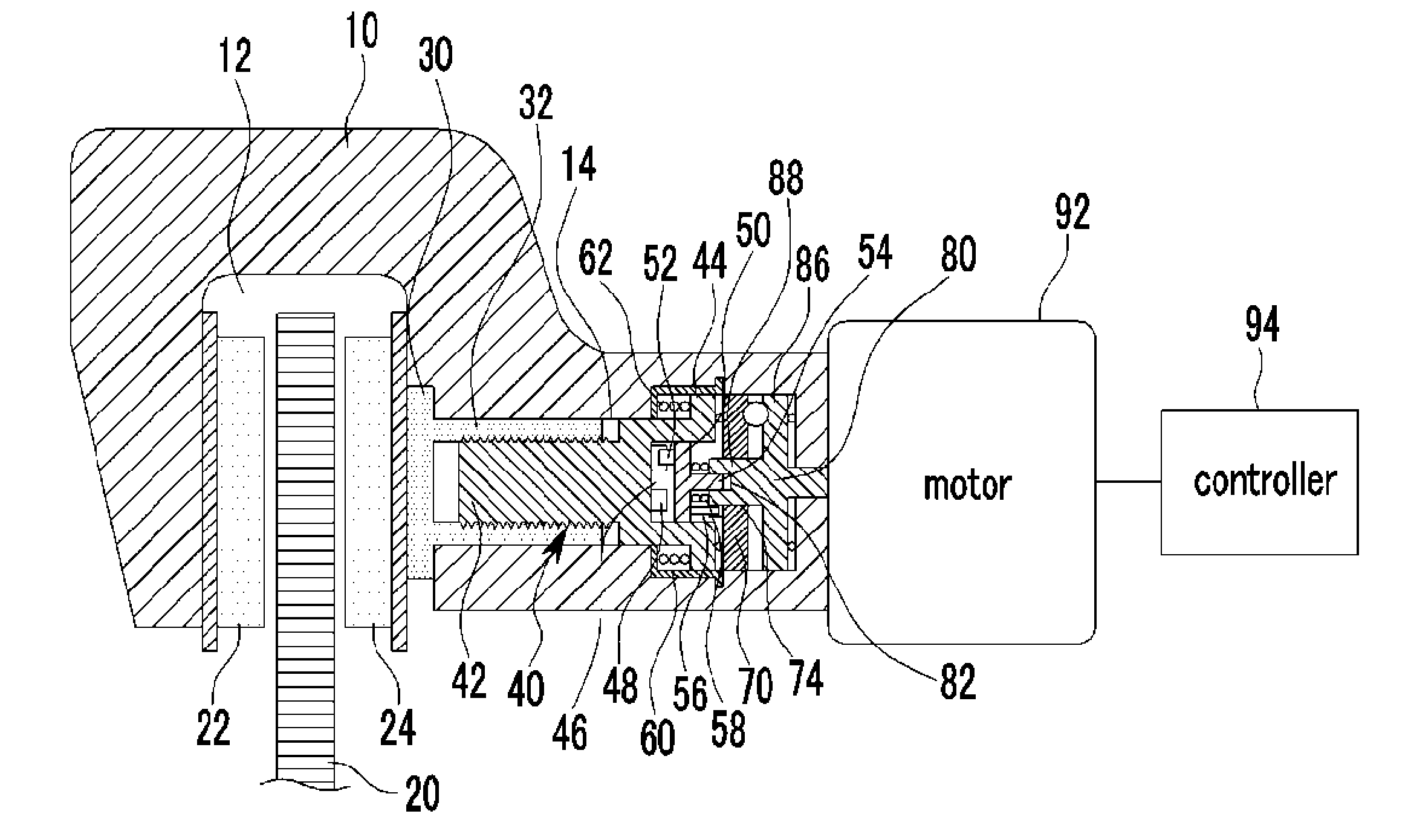
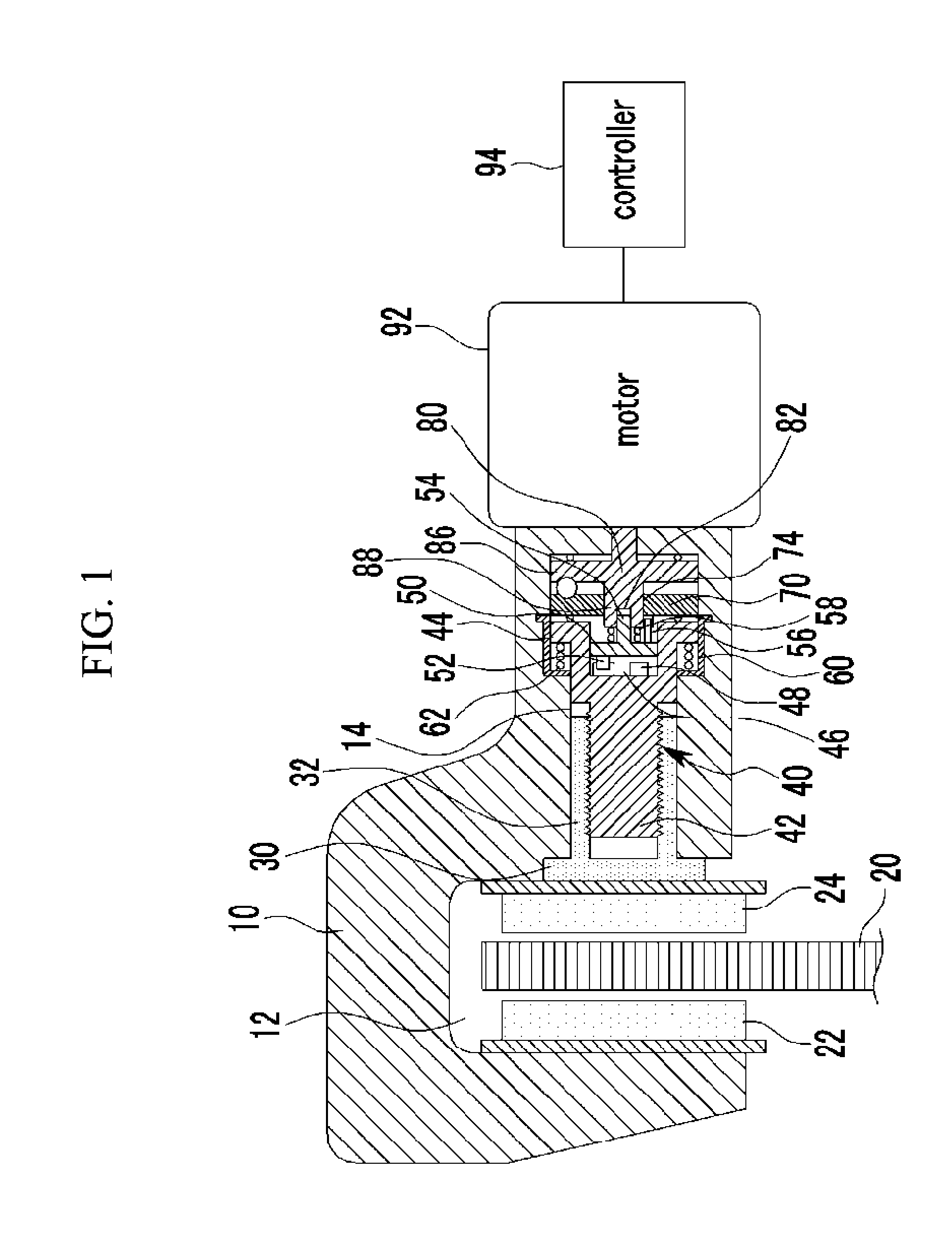
[0033]As shown in FIG. 1, various features of an exemplary electromotive brake system according to the present invention may include a caliper housing 10, a brake disk 20, first and second friction pads 22 and 24, a pressurizing member 30, a push rod 40, an operating disk 50, a non-rotating ramp 70, a rotating ramp 80, a motor 92, and...


PUM


Abstract

An electromotive brake system may include a caliper housing, a first and second friction pads, a brake disk disposed in between, a pressurizing member connected to the second friction pad, a push rod with a push rod groove, an operating disk inserted in the push rod groove, first and second springs, a rotating ramp adapted to convert the rotational movement of a motor into a linear movement of a non-rotating ramp by means of a ball disposed between the rotating ramp and the non-rotating ramp. The electromotive brake system may further include first and second catching portions, a plurality of teeth and corresponding engaging protrusion of the teeth. The plurality of teeth and the protrusion may have slanted or curved surfaces.

Description

CROSS-REFERENCE TO RELATED APPLICATION[0001]The present application claims priority of Korean Patent Application Number 10-2010-0125694 filed in the Korean Intellectual Property Office on Dec. 9, 2010, the entire contents of which application is incorporated herein for all purposes by this reference.BACKGROUND OF THE INVENTION[0002]1. Field of Invention[0003]The present invention relates to an electromotive brake system. More particularly, the present invention relates to an electromotive brake system having high reliability of operation by automatically correcting the abrasion of friction pads.[0004]2. Description of Related Art[0005]Generally, an electromotive brake system, different from a typical hydraulic pressure brake, applies pressure to a friction pad by using mechanical mechanism driven by an electric motor and generates braking force.[0006]A conventional electromotive brake system includes a motor rotating to one direction for braking and to the other direction for releas...

Claims


Application Information

Patent Timeline
Patent Type & Authority Applications(United States)
IPC IPC(8): F16D55/226F16D65/18F16D65/56
CPCF16D55/226F16D2125/36F16D2121/24F16D65/183
Inventor HYUN, DONGYOON
Owner HYUNDAI MOTOR CO LTD
Why Eureka
Try Eureka