

LED lamp
- Summary
- Abstract
- Description
- Claims
- Application Information
AI Technical Summary
Benefits of technology
Problems solved by technology
Method used
Image

Examples
first embodiment
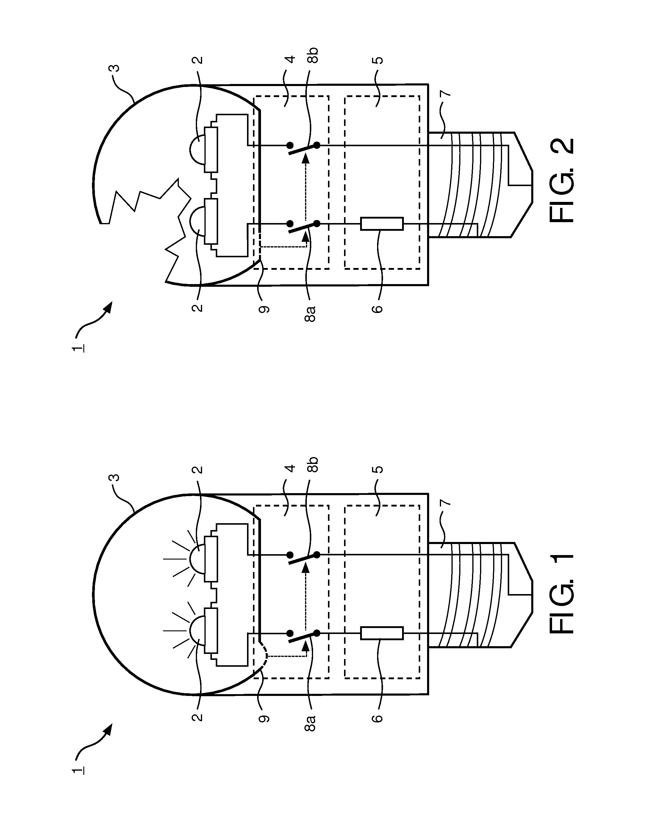
[0094]FIG. 1 shows an LED lamp 1 according to the invention in a schematic side view. The LED lamp 1 comprises two LEDs 2, which are of the ACLED type, adapted for direct connection to mains power, e.g. 220 V. The LEDs 2 are arranged in a lamp housing 3, i.e. a cover member, which is made from transparent plastic material and is bulb-shaped to provide undirected light and to reproduce the directional characteristic of typical incandescent lamps.
[0095]The lamp housing 3 provides electrical isolation for the LEDs 2 and its electrical connections to reduce the risk of electric shock to a user. Especially when replacing the lamp, the user will usually touch the housing 3 of the lamp 1, so that a sufficient electrical isolation is especially important here.
[0096]The housing 3 is pressure-sealed and filled with air at a pressure slightly above ambient pressure.
[0097]The LED lamp 1 further comprises an isolation monitoring device 4 and a ballast unit 5 comprising a series resistor 6 to pro...
second embodiment
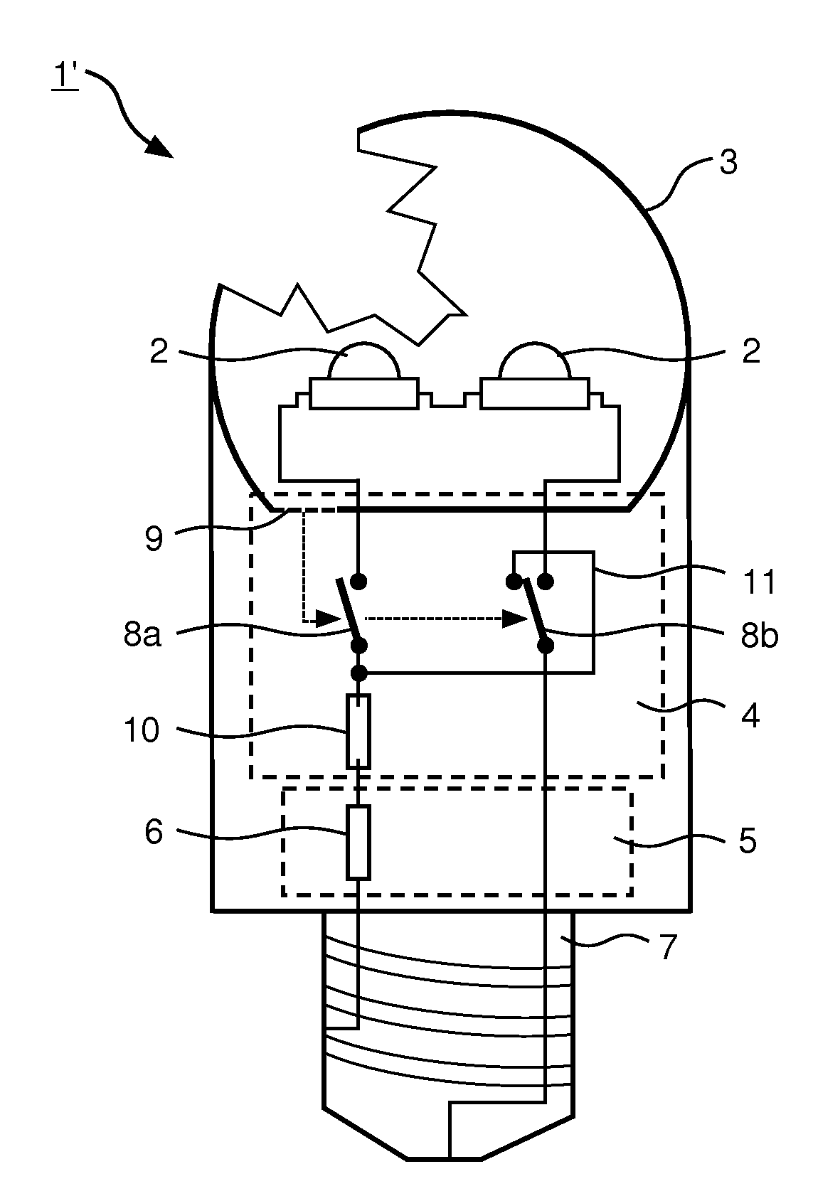
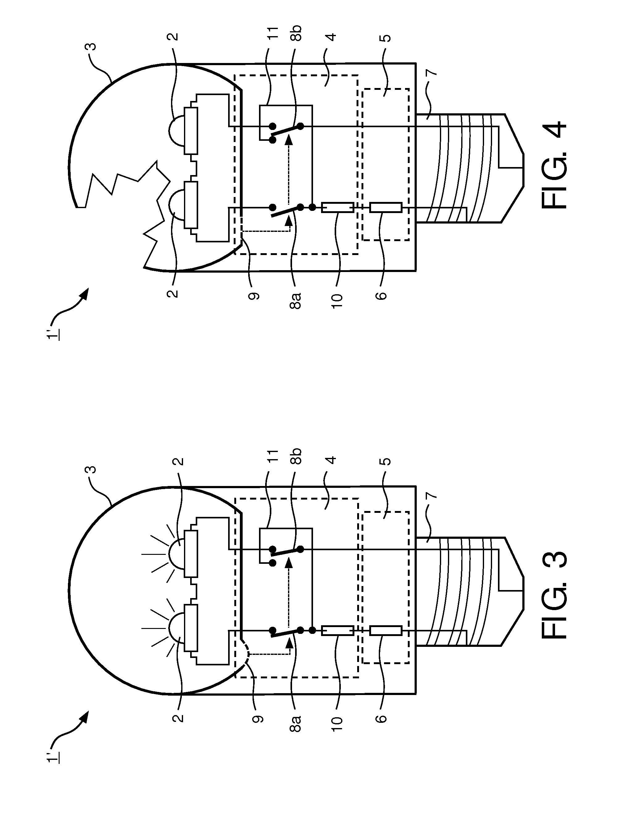
[0102]FIGS. 3 and 4 show an LED lamp 1′. The embodiment of FIG. 3 corresponds to the embodiment of FIG. 1, with the exception that the isolation monitoring device 4 comprises a fuse 10 to further increase the safety of the LED lamp 1′, as explained in the following.
[0103]As can be seen from FIG. 3, the fuse 10 is provided in the supply line in series between the base 7 and the corresponding switch 8a. The switch 8b is provided as a two-way switch, so that the corresponding supply line can be either connected to the LEDs 2 or to a bypass line 11. In case of a defect of the housing 3, the switches 8a and 8b disconnect the LEDs 2 from the mains, as explained above. However, the switch 8b connects the bypass line 11 with the corresponding supply line and thus short-circuits the fuse 10. Consequently, the fuse 11 fails, thereby permanently disconnecting the LEDs 2 from power. The LEDs 2 are thus permanently set to a non-light emissive state.
[0104]According to the present embodiment of th...
fourth embodiment
[0110]an LED lamp 1′″ is shown in FIGS. 7 and 8. The embodiment of the LED lamp 1′″ corresponds substantially to the embodiments explained above, with this difference that the isolation monitoring device 4 comprises a light source 11 and an optical detector 12 to determine a defect of the housing 3.
[0111]The light source 11 is an infrared LED and is arranged to couple emitted light into the housing 3. The emitted light is then guided by the housing 3 by total internal reflection and then received by the detector 12.
[0112]The light source 11 is driven by a controller 13 of the isolation monitoring device 4, e.g. a micro-controller, to emit a signal, which is then received by the detector 12 through the housing 3. The controller 13 then compares the amplitude of the received signal with the sent signal. The difference of the amplitudes is then compared with a maximum amplitude threshold to determine a defect of the housing 3. The amplitude threshold certainly depends on the material, ...
PUM
| Property | Measurement | Unit |
|---|---|---|
| Pressure | aaaaa | aaaaa |
| Power | aaaaa | aaaaa |
| Electric potential / voltage | aaaaa | aaaaa |
Abstract
Description
Claims
Application Information