

A monitoring assembly for battery system of vehicle
A technology of a battery system and a battery management system, applied in the field of monitoring components, can solve the problems of large size, increased structural space and assembly cost, measurement wire wiring and protection technology cost, etc.
- Summary
- Abstract
- Description
- Claims
- Application Information
AI Technical Summary
Problems solved by technology
Method used
Image

Examples
Embodiment Construction
[0040] In the following figures, the same reference signs are also used for the same technical features of the different exemplary embodiments.
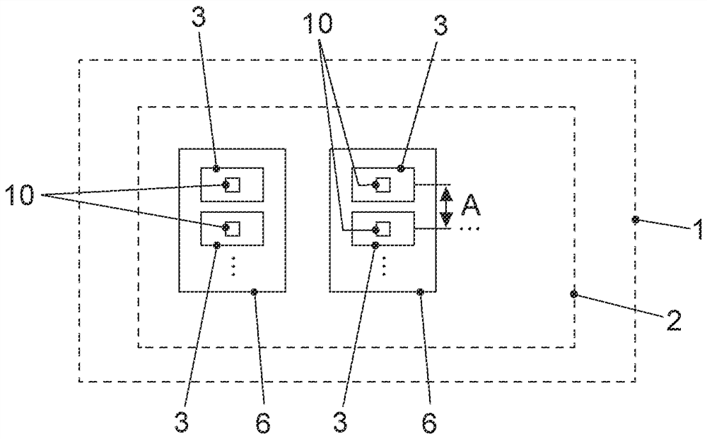
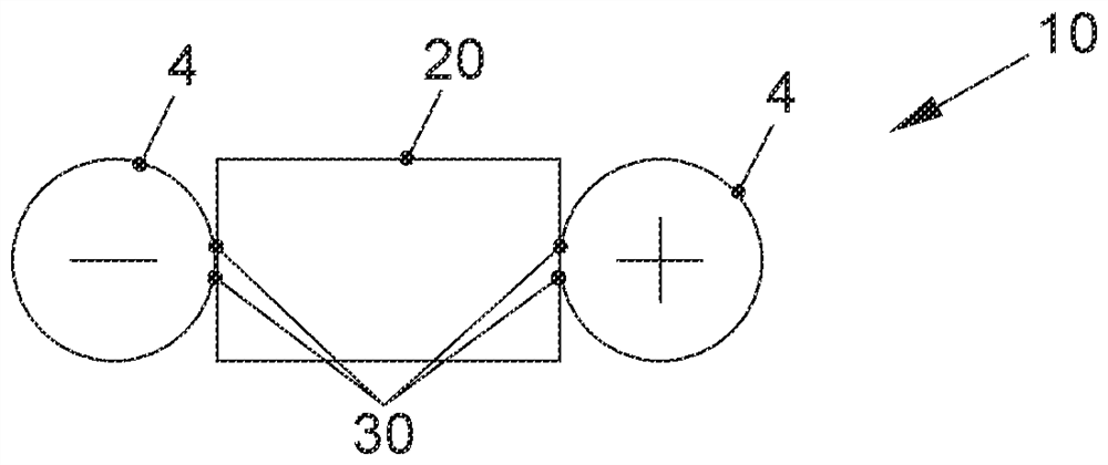
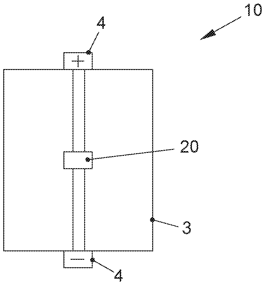
[0041] exist Figures 1 to 6 A monitoring arrangement 10 according to the invention for a battery system 2 of a vehicle 1 is shown in . It can be seen here that at least one electronic processing unit 20 is provided, which is (correspondingly) assigned to exactly one battery cell 3 of the battery system 2 . For example, the processing device 20 can be attached directly to the battery unit 3 . In addition, two parallel electrical connection means 30 at the (respective) processing means 20 can provide electrical contacts by means of which the processing means 20 are redundantly electrically connected to the (same) potential of the battery cells 3 . Two connection means 30 can have the same function in parallel and provide the electrical connection in the same way (with equal potential), so that there is corresponding redundancy. Exe...
PUM
 Abstract
Description
Claims
Application Information