Power Transfer System and Noncontact Charging Device

a technology of power transmission system and charging device, which is applied in the direction of electrical apparatus construction details, transportation and packaging, and support structure mounting, etc., can solve the problems of unnecessary electric field, increased voltage applied to each electrode, and reduced flexibility of arrangement of both power transmission device and power reception devi

Active Publication Date: 2012-06-14
MURATA MFG CO LTD
View PDF5 Cites 10 Cited by
  • Summary
  • Abstract
  • Description
  • Claims
  • Application Information

AI Technical Summary

Problems solved by technology

Therefore, there is a problem that the flexibility of arrangement of both the power transmission device and the power reception device is considerably low.
Therefore, there is a problem that a voltage applied to each electrode increases.
Furthermore, because the periphery of each electrode is not shielded, there

Method used


Image

  • Power Transfer System and Noncontact Charging Device
  • Power Transfer System and Noncontact Charging Device
  • Power Transfer System and Noncontact Charging Device

Examples


first embodiment

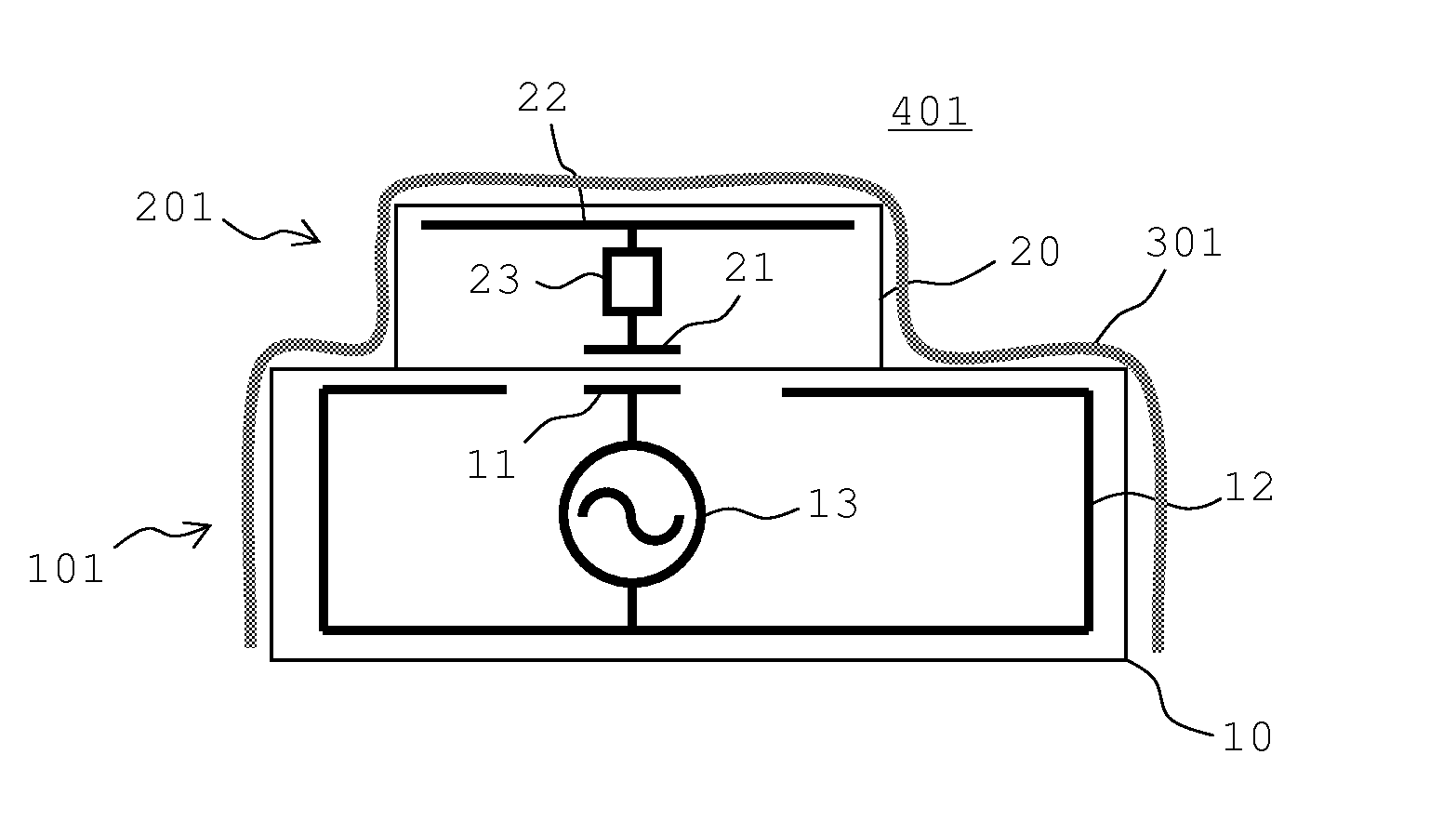
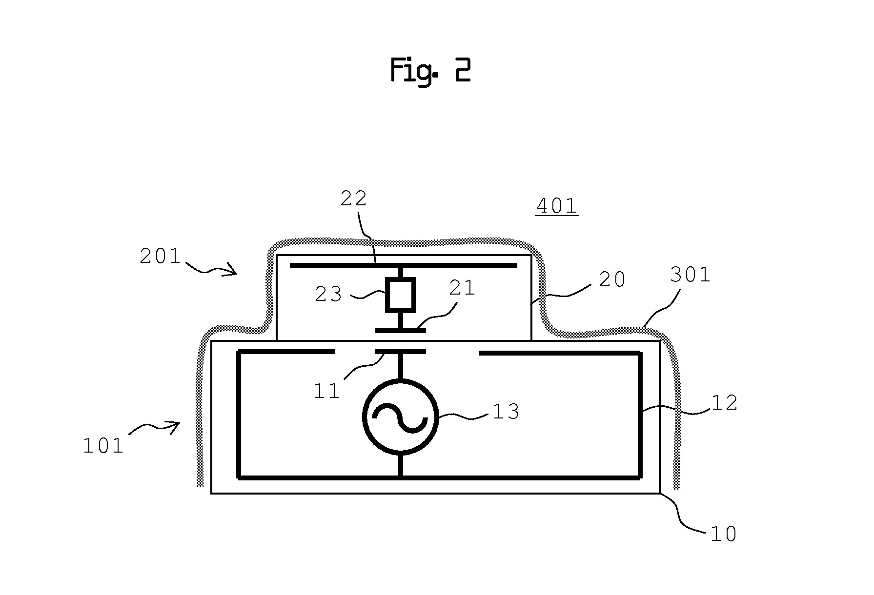
[0026]The configuration of a power transfer system according to a first embodiment will be described with reference to FIG. 2 to FIG. 4. FIG. 2 is a cross-sectional view that conceptually shows a relevant portion of a power transfer system 401. The power transfer system 401 includes a power transmission device 101 and a power reception device 201. A high-voltage side conductor 11 and a low-voltage side conductor 12 are formed near the upper surface of a casing 10 of the power transmission device 101. The low-voltage side conductor 12 surrounds the high-voltage side conductor 11 in an insulated state from the high-voltage side conductor 11. In addition, an alternating voltage generating circuit 13 is provided inside the casing 10 of the power transmission device 101 and applies an alternating voltage between the high-voltage side conductor 11 and the low-voltage side conductor 12. In this example, the low-voltage side conductor 12 is arranged along the outer peripheral surface of the...

second embodiment

[0046]FIG. 5 is a cross-sectional view that conceptually shows a relevant portion of a power transfer system 402 according to a second embodiment. The power transfer system 402 includes a power transmission device 102 and a power reception device 202.

[0047]In the example shown in FIG. 2, the power reception device 201 is placed on the power transmission device 101. FIG. 5 shows an example in which the power transmission device 102 and the power reception device 202 are arranged side by side. As shown in FIG. 5, a high-voltage side conductor 11 is provided at the side of the power transmission device 102, a high-voltage side conductor 21 is provided at the side of the power reception device 202, and a capacitive coupling conductor 302 covers the power transmission device 102 and the power reception device 202 that are arranged side by side. In this manner, it is possible to achieve capacitive coupling.

third embodiment

[0048]FIG. 6 is a cross-sectional view that conceptually shows a relevant portion of a power transfer system 403 according to a third embodiment. The configuration of the power transfer system 403 differs from that shown in FIG. 2 in that the capacitive coupling conductor 302 is electrically continuous with the low-voltage side conductor 12 of the power transmission device 103. With the above configuration, a capacitance generated between the capacitive coupling conductor 302 and the low-voltage side conductor 22 is directly connected between the low-voltage side conductors 12 and 22. Thus, it is possible to increase (gain) a capacitance between the low-voltage side conductors 12 and 22.


PUM


Abstract

A power transfer system includes a power transmission device, a power reception device and a capacitive coupling conductor. A high-voltage side conductor is formed near the upper surface of a casing of the power transmission device, and a low-voltage side conductor is formed near the lower or surrounding surface of the casing. The power transmission device includes an alternating voltage generating circuit. A high-voltage side conductor is formed near the lower surface of a casing of the power reception device, and a low-voltage side conductor is formed near the upper surface of the casing of the power reception device. The power reception device includes a load circuit. The high-voltage side conductors are capacitively coupled to each other when facing each other, and the low-voltage side conductors are capacitively coupled to each other via a capacitive coupling conductor.

Description

CROSS REFERENCE TO RELATED APPLICATIONS[0001]The present application is a continuation of International application No. PCT / JP2009 / 002925, filed Jun. 25, 2009, the entire contents of which is incorporated herein by reference.FIELD OF THE INVENTION[0002]The invention relates to a power transfer system that transfers electric power in a noncontact manner and a noncontact charging device that uses the power transfer system.BACKGROUND OF THE INVENTION[0003]Patent Document 1 and Patent Document 2 describe existing techniques related to a noncontact power transfer system. The power transfer system described in Patent Document 1 increases the efficiency of power transfer between a card reader / writer and a noncontact-type card. Two electrodes are provided for each of the card reader / writer and the noncontact-type card. When power is transferred, the electrodes of the card reader / writer face the electrodes of the noncontact-type card in a pair to transfer electric power through capacitive co...

Claims


Application Information

Patent Timeline
IPC IPC(8): H02J7/06H02J1/00H02J7/00
CPCH02J7/025H02J7/0042H02J50/12H02J50/70H02J50/05
Inventor ICHIKAWA, KEIICHIBONDAR, HENRI
Owner MURATA MFG CO LTD
Why Eureka
Try Eureka