
Inductor

a technology of inductance and shielding layer, applied in the direction of transformer/inductance details, fixed inductances, etc., can solve the problems of increasing material cost, easy scratching of the insulation layer of enameled wire, waste of enameled wire, etc., to save labor and material, improve working efficiency, and reduce the effect of design

Inactive Publication Date: 2012-06-14
LOTES
View PDF5 Cites 11 Cited by
  • Summary
  • Abstract
  • Description
  • Claims
  • Application Information

AI Technical Summary

Benefits of technology

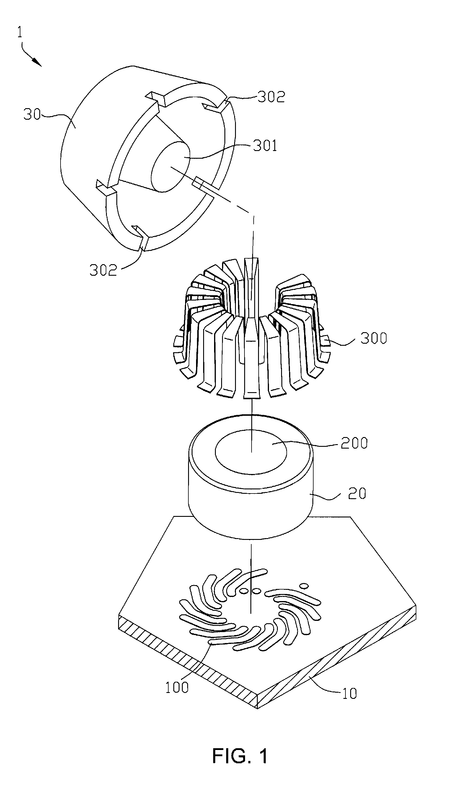
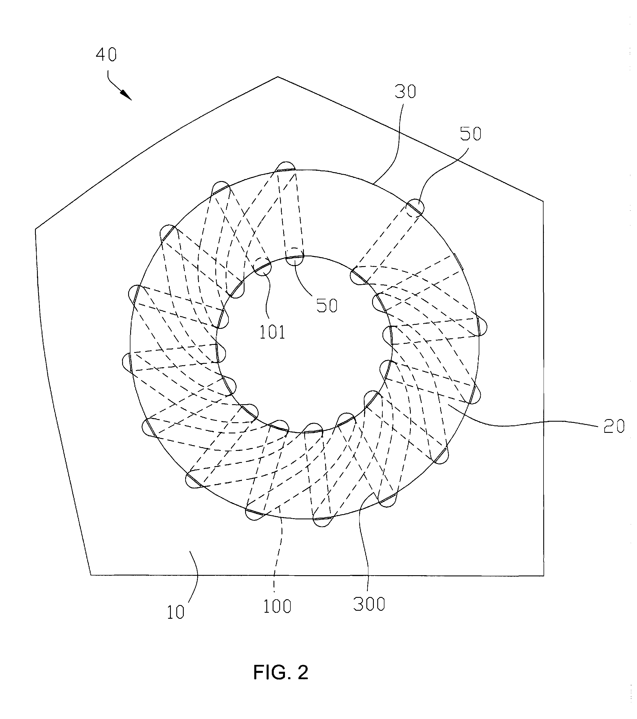
[0008]Compared with the prior art, multiple upper conducting layers are arranged on the surface of the insulating cover, and multiple lower conducting layers are arranged on the substrate, so that the coil can be formed simply by alternately connecting the upper conducting layers and the lower conducting layers. Therefore, in one aspect, the inductor of the present invention does not require winding a coil in advance, which can save much labor and material and improve the working efficiency. Furthermore, as the upper conducting layers located on the insulating cover are directly arranged on the surface of the insulating cover, no extra space is occupied, and thus the design is miniaturized.

Problems solved by technology

Thus, the insulating layer of the enameled wire is easily scratched during the coil winding process.
In addition, it is necessary to reserve a segment at the front end of the enameled wire when the enameled wire is wound so as to fasten the enameled wire during the winding process, which inevitably results in a waste of the enameled wire after the winding operation is completed, thereby increasing the cost of material.
Besides, the manual coil winding is time- and labor-consuming and inefficient, while the automatic coil winding results in a high cost.
Furthermore, the enameled wire and the magnetic core are independent components and occupy a lot of space, which is not conducive to miniaturization of the product design.
Therefore, a heretofore unaddressed need exists in the art to address the aforementioned deficiencies and inadequacies.

Method used


Image

  • Inductor
  • Inductor
  • Inductor

Examples


Embodiment Construction

[0024]The present invention is more particularly described in the following examples that are intended as illustrative only since numerous modifications and variations therein will be apparent to those skilled in the art. Various embodiments of the invention are now described in detail. Referring to the drawings, like numbers indicate like components throughout the views. As used in the description herein and throughout the claims that follow, the meaning of “a”, “an”, and “the” includes plural reference unless the context clearly dictates otherwise. Also, as used in the description herein and throughout the claims that follow, the meaning of “in” includes “in” and “on” unless the context clearly dictates otherwise.

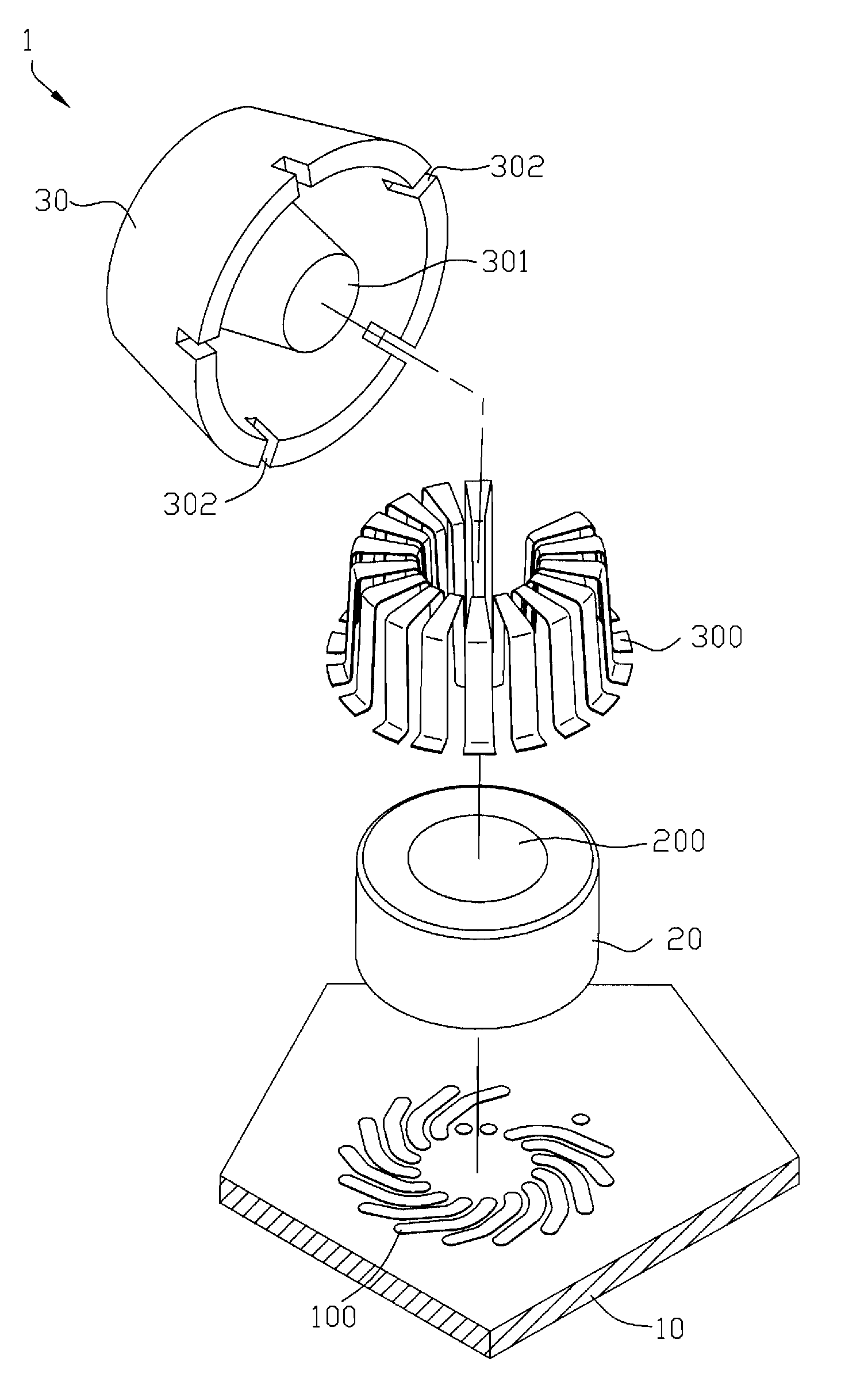
[0025]Referring to FIGS. 1 and 2, a first embodiment of the present invention provides an inductor 1, including: a substrate 10, arranged with multiple lower conducting layers 100, a magnetic core 20, disposed on the substrate 10, and an insulating cover 30, covering the ...


PUM

PropertyMeasurementUnit
conductingaaaaaaaaaa
magneticaaaaaaaaaa
inductanceaaaaaaaaaa

Abstract

In one embodiment, the inductor includes: a substrate, arranged with multiple lower conducting layers, a magnetic core, disposed on the substrate, and an insulating cover, covering the substrate and wrapping the magnetic core. Multiple upper conducting layers are arranged on a surface of the insulating cover. The upper conducting layers and the lower conducting layers are alternately connected to form at least one coil winding around the magnetic core. Two ends of the coil are respectively used to conduct external electrical signals.

Description

CROSS-REFERENCE TO RELATED APPLICATIONS[0001]This non-provisional application claims priority under 35 U.S.C. §119(a) on Patent Application No. 201020663976.4 filed in China on Dec. 8, 2010, the entire contents of which are hereby incorporated by reference.FIELD OF THE INVENTION[0002]The present invention relates to an inductor, and more particularly to an inductor which does not require winding a coil.BACKGROUND OF THE INVENTION[0003]An inductor commonly seen in the industry has a magnetic core and an enameled wire wound on an outer periphery of the magnetic core, in which the enameled wire is wound manually or automatically in advance.[0004]In order to obtain more inductance, generally it is necessary to superpose the enameled wire during the coil winding process. Thus, the insulating layer of the enameled wire is easily scratched during the coil winding process. In addition, it is necessary to reserve a segment at the front end of the enameled wire when the enameled wire is wound...

Claims


Application Information

Patent Timeline
Patent Type & Authority Applications(United States)
IPC IPC(8): H01F27/28
CPCH01F17/0033H01F2027/2814H01F27/027H01F17/062
Inventor SHAO, CHIH PING
Owner LOTES
Learn More