
Translating multifocal eyeglass lenses

a technology of multifocal and eyeglass lenses, applied in the field of translating multifocal eyeglass lenses, can solve the problems of blurred tv picture, wearer's eyeglass lens may interfere with the screen of the tv, and not an optimal solution

Active Publication Date: 2012-06-14
ESSILOR INT CIE GEN DOPTIQUE
View PDF8 Cites 37 Cited by
  • Summary
  • Abstract
  • Description
  • Claims
  • Application Information

AI Technical Summary

Benefits of technology

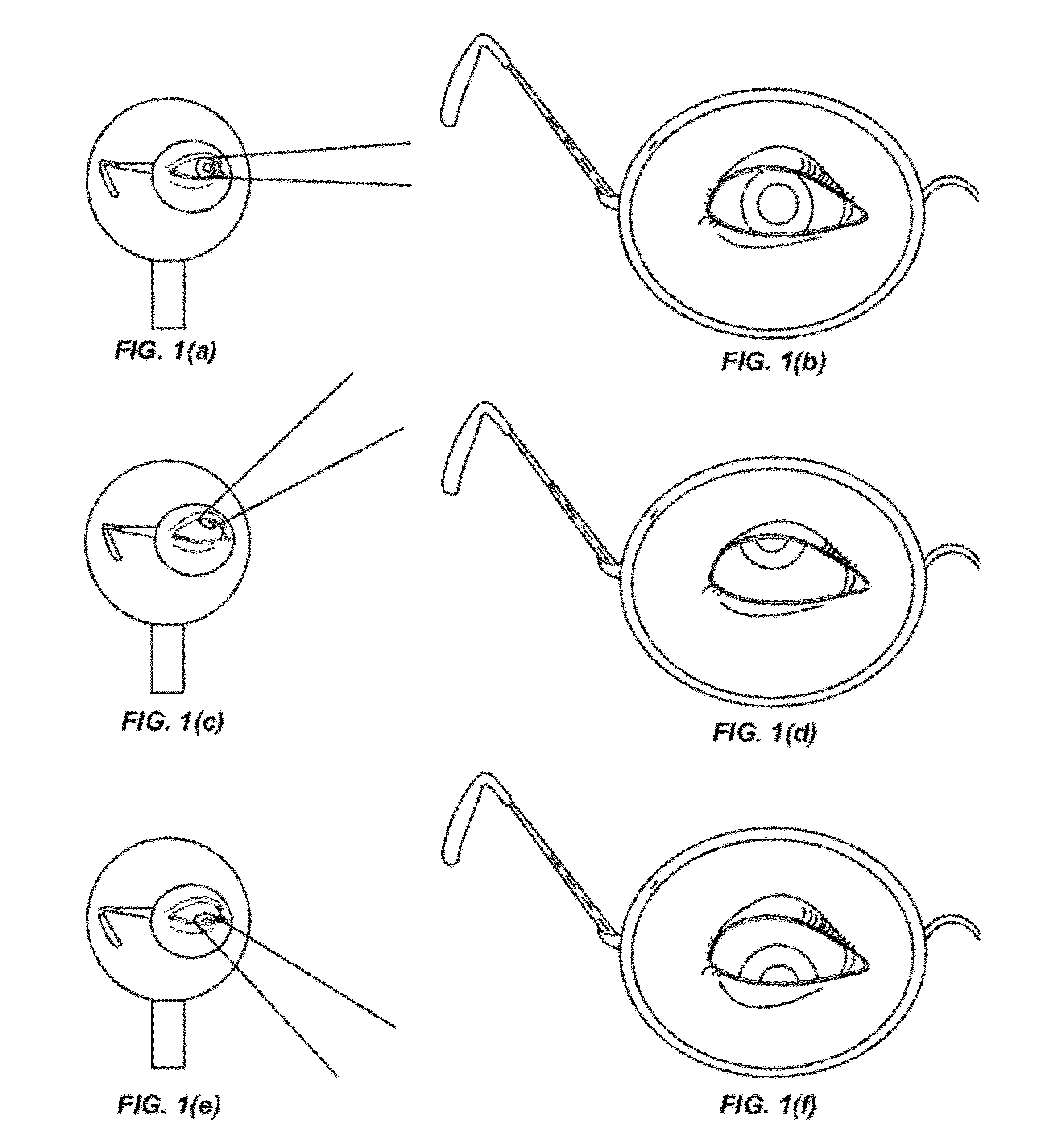
The patent describes eyewear that provides optical power for both day and night time viewing. The eyewear includes a lens with two optical zones that provide different levels of optical power. The lens can move or adjust its position to optimize the optical power for the wearer's eye. The eyewear can also include a progressive addition surface or a third and fourth optical zone to provide additional optical power for the wearer's intermediate and near distance optical power needs. The optical power of the first and second optical zones can vary continuously or discontinuously between them. The lens can have a curved surface to decrease or increase optical power as the distance from the wearer's eye increases. The eyewear can also include a movable member that adjusts the position of the lens to optimize optical power for the wearer's eye. Overall, the eyewear provides a wide range of optical power for both day and night time viewing.

Problems solved by technology

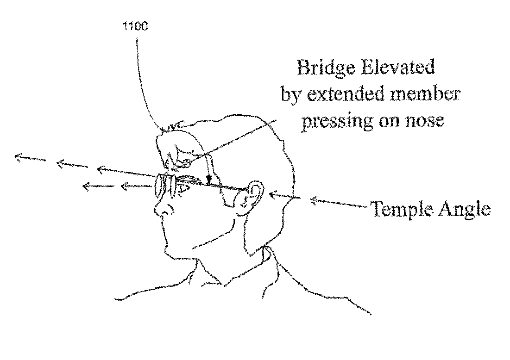
Existing multi-focusing eyeglasses, whether lined bifocal, trifocal, or no-lined progressive addition lenses may have disadvantages for certain lifestyle settings such as lying in bed when watching TV and trying to read a book.
For example, when reclining in bed, the near area of the wearer's eyeglass lens may interfere with the screen of the TV and blur the TV picture.
While this may temporarily solve or alleviate the immediate problem it is not an optimal solution.
The wearer may attempt to look down at the stairs but in so doing, may look though a portion of the lens that is designed to provide a different optical power—thereby resulting in blurry vision (and perhaps disorientation or injury).

Method used


Image

  • Translating multifocal eyeglass lenses
  • Translating multifocal eyeglass lenses
  • Translating multifocal eyeglass lenses

Examples


Embodiment Construction

[0071]Some terms that are used herein are described in further detail as follows:

[0072]As used herein, “add power” may refer to the optical power added to the far distance viewing optical power which is required for clear near distance viewing in a lens. For example, if an individual has a far distance viewing prescription of −3.00D with a +2.00D add power for near distance viewing then the actual optical power for near distance is −1.00D. Add power may sometimes be referred to as plus power. Add power may be further distinguished by referring to “near viewing distance add power,” which refers to the add power in the near viewing distance portion of the optic and “intermediate viewing distance add power” may refer to the add power in the intermediate viewing distance portion of the optic. Typically, the intermediate viewing distance add power may be approximately 50% of the near viewing distance add power. Thus, in the example above, the individual would have +1.00D add power for in...


PUM


Abstract

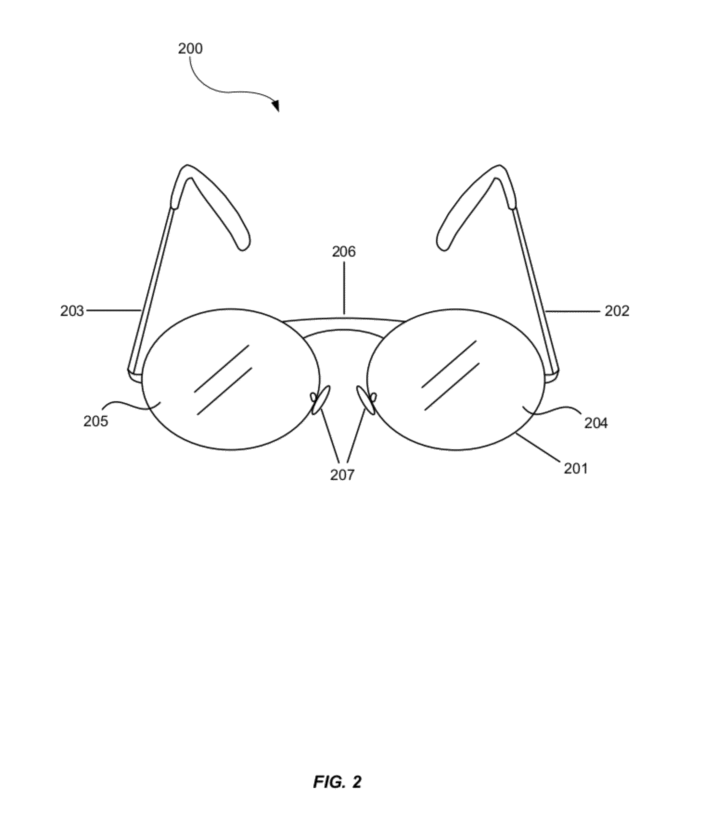
Embodiments may provide multifocal eyeglass lenses and eyewear that may comprise multifocal translating eyeglass lenses. The eyewear may comprise a lens housing, a first temple and a second temple coupled to the lens housing, and a first and a second lens supported by the lens housing. The lens may comprise a first optical zone having an optical power corresponding to a wearer's far distance day time optical power need and a second optical zone having an optical power corresponding to a wearer's far distance night time optical power need. The eyewear may further comprise a movable member coupled to the lens housing, the first temple, or the second temple, wherein the movable member may be configured to move between a first position and a second position, where a position of the lens may be based at least in part on the position of the movable member. The eyewear may further include a mechanism adapted to adjust the position of the movable member.

Description

CROSS-REFERENCES TO RELATED APPLICATIONS[0001]This application claims benefit under 35 U.S.C. §119(e) of U.S. provisional patent application No. 61 / 420,796, filed on Dec. 8, 2010; U.S. provisional patent application No. 61 / 452,441, filed on Mar. 14, 2011; U.S. provisional patent application No. 61 / 509,632, filed on Jul. 20, 2011; and U.S. provisional patent application No. 61 / 552,506, filed on Oct. 28, 2011. The entire disclosure of each of these applications is incorporated herein by reference for all purposes and in their entireties.BACKGROUND[0002]Existing multi-focusing eyeglasses, whether lined bifocal, trifocal, or no-lined progressive addition lenses may have disadvantages for certain lifestyle settings such as lying in bed when watching TV and trying to read a book. For example, when reclining in bed, the near area of the wearer's eyeglass lens may interfere with the screen of the TV and blur the TV picture. A wearer may attempt to solve this issue by raising the temples of ...

Claims


Application Information

Patent Timeline
Patent Type & Authority Applications(United States)
IPC IPC(8): G02C7/06
CPCG02C7/06G02C5/124G02B27/017G02B2027/0178G02C7/065G02C7/066
Inventor LOEB, JR., JACKBLUM, RONALD D.
Owner ESSILOR INT CIE GEN DOPTIQUE
Learn More